Guys are accessible through their related pole's Components list on the Poles tab.
Managing Guys
Add Guying
Overhead Design Analysis (OHDA) supports several guying configurations:
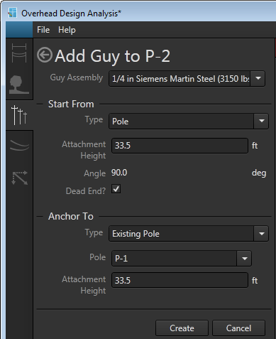
Add guy form
Quick Steps
Follow these general steps to add guying to a scenario:
- Select a pole for the new guying.
- Click Add Component from the Pole's Components list on the Poles tab.
- Select Guy from the drop-down menu. This opens the Add Guy form.
- Select the assembly from the Guy Assembly drop-down list.

Use the keyboard to quickly navigate the list. Pressing a key will jump to the next item in the list that begins with that letter or number. - In the Start From section, set the Type, Attachment Height, and the Dead End designation.
- In the Anchor To section, set the Type of anchor and enter relevant values for that type.
- Click Create. The guying and its attachment point are added to the canvas. Blue shading signals the additions are not added to the scenario yet.
- Click Calculate to analyze the updated scenario. The new equipment is now added to the scenario and is no longer shaded blue on the canvas.
Down Guying
Follow these steps to add down guying to a scenario:
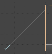
Down guying
- Select a pole for the new guying under Poles in Profile or in the Plan view.
- Select the Components option for the pole on the Poles tab.
- Click the Add Component button.
- Select Guy from the drop-down menu. This opens the Add Guy form.
- Select the guying assembly from the available options in the Assembly drop-down menu.
- In the Start From section, select Pole to secure one end of the guying to the currently selected pole.
- Set the Attachment height. OHDA outlines the field in red to signal an input error if the Attachment Height is greater than the pole height.
- Select the Dead End checkbox for dead end guying.
- In the Anchor To section, select Surface as the Type.
- Click New if a new anchor is needed for the guying. Otherwise, select Existing to secure the guying to an anchor already in the scenario. If there's not an existing anchor available, the list is empty and the field is bordered in red to signal the error.
- If the anchor is new, enter the required values. Otherwise, select an existing anchor.
- Click Create. The guying and anchor are added to scenario. The anchor is shaded blue until you click Calculate.
- Click Calculate to analyze the updated scenario. The guying and anchor are added to the scenario and the anchor is no longer shaded blue.
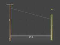
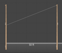
Span Guying
 |
If a span guy violates a clearance rule vertically, then it will be flagged as a violation regardless of its horizontal clearance. |
Follow these steps to add span guying to a scenario:
Span guying
- Select a pole for the new guying under Poles in Profile or in the Plan view.
- Select the Components option for the pole on the Poles tab.
- Click the Add Component button.
- Select Guy from the drop-down menu. This opens the Add Guy form.
- Select the guy assembly from the available options in the Assembly drop-down menu.
- In the Start From section, select Pole to secure one end of the guying to the currently selected pole.
- Set the Attachment height. OHDA outlines the field in red to signal an input error if the Attachment Height is greater than the pole height.
- In the Anchor To section, select Existing Pole as the Type.
- Select the anchoring pole from the drop-down list. This list is populated with the pole or poles directly adjacent to the targeted pole in the main profile and secondary profile if the pole is part of one.
- Set the attachment height of the guying to the anchoring pole. OHDA outlines the field in red to signal an input error if the Attachment Height is greater than the pole height.
- Click Create. The guying is added to the canvas.
- Click Calculate to analyze the updated scenario.
Span Guying to an Adjacent Pole
Follow these steps to add span guying to an adjacent pole in a scenario:
Span guying to an adjacent pole
- Select a pole for the new guying under Poles in Profile or in the Plan view.
- Select the Components option for the pole on the Poles tab.
- Click the Add Component button.
- Select Guy from the drop-down menu. This opens the Add Guy form.
- Select the guying assembly from the available options in the Assembly drop-down menu.
- In the Start From section, select Pole to secure one end of the guying to the currently selected pole.
- Set the Attachment height. OHDA outlines the field in red to signal an input error if the Attachment Height is greater than the pole height.
- In the Anchor To section, select Existing Pole as the Type if the adjacent pole already exists in the scenario. If the adjacent pole has not been created yet, select New Stub Pole.
The New Stub Pole option is only available if the currently selected pole does not already have an adjacent pole connected to it. - Enter values for the attachment pole:
- Existing Pole
- Select the existing adjacent pole in the Type field. Take care to choose the correct pole as poles in the main profile will also be included in the list of available poles.
- Enter the attachment height. OHDA outlines the field in red to signal an input error if the Attachment Height is greater than the pole height.
- New Stub Pole
- Selecting New Stub Pole adds a potential pole to the canvas shaded in blue and creates a secondary profile.
- Set the values for the new pole in the Pole and Line Angle sections. See the add adjacent pole section for more details.
- Existing Pole
- Click Create. The guying is added to the canvas. If an adjacent pole was created, it remains on the Profile view canvas as a blue dotted outline and shaded blue in the 3D view.
- Click Calculate to analyze the updated scenario. If a stub pole was created, it is added to the scenario in a new profile with the blue shading and outline removed.
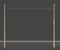
Sidewalk guying
Follow these steps to add sidewalk guying to a scenario:
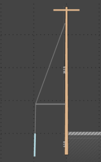
Sidewalk guying
- Select a pole for the new guying under Poles in Profile or in the Plan view.
- Select the Components option for the pole on the Poles tab.
- Click the Add Component button.
- Select Guy from the drop-down menu. This opens the Add Guy form.
- Select the guying assembly from the available options in the Assembly drop-down menu.
- In the Start From section, select Pole and Strut from the Type drop-down list.
- Set the attachment height of the guying to the selected pole. OHDA outlines the field in red to signal an input error if the Attachment Height is greater than the pole height.
- Set the Strut Height in feet from the ground's surface.
- Set the Strut Length in feet and Strut Diameter in inches.
- Because the sidewalk guy must be anchored to the ground, the Type field in the Anchor To section is deactivated.
- Set the Assembly, Guy Lead, Angle, and Soil Type.
- Click Create. The pole, strut, and anchor are added to the canvas. The anchor is outlined with a blue dotted line in the Profile view and highlighted in blue in the 3D view.
- Click Calculate to analyze the updated scenario. The equipment is added to the scenario with the blue shading and outline removed from the anchor.
Arm Guying
Follow these steps to add arm guying to a scenario:
Arm guying
- Select a pole for the new guying under Poles in Profile or in the Plan view.
- Select the Components option for the pole on the Poles tab.
- Click the Add Component button.
- Select Guy from the drop-down menu. This opens the Add Guy form.
- Select the guying assembly from the available options in the Assembly drop-down menu.
- In the Start From section, select Arm from the Type drop-down list.
- Select the cross arm to target from the Assembly drop-down list that is populated with the assemblies for the currently selected pole.
- Enter the number of guy wires (between one and four) to attach to the cross arm in the Quantity field.
- Select the Dead End checkbox if true.
- In the Anchor To section, select either Existing Pole or New Stub Pole from the Type drop-down list.
- Enter values for the attachment pole:
- Existing Pole
- Select the existing adjacent pole for attachment in the Type field. The drop-down list is populated with poles directly adjacent to the currently selected pole in both primary and adjacent profiles.
- Enter the attachment height. OHDA outlines the field in red to signal an input error if the Attachment Height is greater than the pole height.
- New Stub Pole
- Selecting New Stub Pole creates a secondary profile and adds a potential pole to the Profile view canvas outlined in a blue dotted line.
- Set the values for the new pole in the Pole and Line Angle sections. See the add adjacent pole section for more details.
- Existing Pole
- Click Create. The guying is added to the canvas.
- Click Calculate to analyze the updated scenario.
Edit Guying
Follow these steps to edit guying in a scenario:
- On the Poles tab, select the pole with the guy you want to edit attached.
- In the Components list of the currently selected pole, double-click the guy you want to target for editing. Alternatively, you can double-click the guy to edit directly in the 3D view canvas. This opens the Edit Guy form.
Arm guying is associated with its attached assemblies, so you must expand the assembly's list of attachments in the pole's Components list to select. - Edit values as needed. Values that cannot be edited are disabled.
- Click Calculate to analyze the updated scenario.
Delete Guying
Click the red X next to the guying you want to delete in the Components list on the Poles tab. The guying is immediately removed from the canvas.
Any anchors associated with the deleted guying will turn red in the Poles tab but will remain on the canvas. The abandoned anchors must be deleted or connected to new guying before you can analyze a scenario.
|
Arm guying is associated with its attached assemblies, so you must expand the assembly's list of attachments in the pole's Components list to delete. |
OHDA and Multiple Guy Wires on the Same Pole
OHDA assumes that forces spread across multiple guy wires attached to the same pole in any configuration are equal.
