Primary poles form the main profile of the scenario. Adjacent poles form secondary profiles for circuit taps and span guying.
Managing poles in your scenario:
Adding Poles
Follow these general steps to place a new pole in a scenario:
- Select an existing primary pole to which you will attach the new pole. You can select an existing pole by clicking the pole in the Poles in Profile list, or by clicking a pole or cycling through poles in the Plan view.
- On the Poles tab, click the plus (+) symbol next to Poles in Profile. Select Primary or Adjacent from the drop-down menu.
- Add a Primary Pole - Added to the main, inline profile of a scenario.
- Add an Adjacent Pole - Not part of the main profile. Used for support of a pole in the main profile, or to analyze the effects of a tap-off on a pole in the main profile. Creating an Adjacent pole will also create a secondary profile.
- The Add Pole form appears in the left pane.
 |
The plus (+) symbol is inactive when the selected pole is an adjacent pole because only one adjacent pole can exist in a secondary profile. |
|
A primary pole can only have one adjacent pole. As a result, the option for adjacent pole in the add pole drop-down menu is unavailable for poles already connected to an adjacent pole. |
Follow these steps to place a primary pole in a scenario:
- Select values for the pole's attributes. By default, the attributes of the pole you selected to attach to are applied to the new pole. Modify them as needed.
The Reference Pole field allows you to change which pole the new pole attaches to in the profile. Other field values do not automatically change to match a new reference pole selection. - If the new pole is placed between existing poles, set the line angle for the incoming line. This value defaults to 0°.
In OHDA, the 0° reference point is not a point on the screen, but is set to the incoming line of the backline pole.
- Select the Include downstream poles in pivot checkbox if you want the poles following the targeted pole in a profile to continue along that same angle. Clear the checkbox to leave other poles in the same place. OHDA will automatically calculate the Incoming Angle of downstream poles.
- Click Create.
- The Profile view depicts the new pole using a blue dotted line. In 3D view, a blue pole is shown. The pole will not be added to the scenario until you click Calculate, as seen in Figure 1. Proposed poles are indicated with an asterisk in the Poles in Profile list.
- Click Calculate. The proposed pole is added to the scenario with existing cables in the profile extended to or through the new pole position. The pole will inherit the assemblies of the reference pole by default, including attachment height. Any added poles will appear in the list beneath the Poles in Profile heading.
Follow these steps to add an adjacent pole to a scenario:
- Select values for the pole's attributes. By default, the attributes of the pole you selected to attach to are applied to the new pole. Modify them as needed.
Creating a new adjacent pole also creates a secondary profile. Consequently, the Reference Pole cannot be changed in the Add Pole form because there is only one existing pole in the profile. The Profile view changes to display only the proposed secondary profile. - Set the line angle for the incoming line. This value defaults to 90°.
- Click Calculate. A new adjacent pole is created in a new secondary profile. Any adjacent poles appear in the pole list associated with their reference poles.
 |
You cannot attach cables from the primary profile and the secondary profile to the same assembly. |
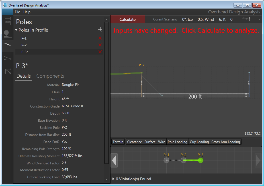
Figure 1, New pole added to scenario
Edit a Pole
Targeting a pole for editing:
- Double-click the pole name in the Poles in Profile section of the Poles tab
- Double-click the pole in 3D view
Targeting a pole for editing opens the Edit Pole form. Here you can edit most the attributes associated with that pole. You cannot, however, change the backline pole, distance from the backline pole, or the Dead End designation. If you need to edit these values, you must delete the current pole and create a new one with the corrected values.
Editing a pole's height also affects any assemblies, guying, transformers, or switches associated with the pole. Because the position of these items is based on the top of the pole, a taller pole will increase the distance from ground for transformers, switches, assemblies, and guying attachment points. A shorter pole will bring these items closer to the ground. Both cases affect load calculations.
Editing a primary pole's base elevation will also set the base elevation of any associated adjacent poles to the same value.
Apply to All
Allows you to apply the selected attribute values to all poles in the scenario. You can click the triangle on the right of the button to access the drop-down selection of attributes to apply. Select the attributes you want applied to all poles in the profile. All attributes are selected by default.Click the circled arrow next to Edit Pole to close the Edit Pole form and return to the Poles tab.
Delete a Pole
On the Poles tab, click the red X next to the pole you wish to delete. The deleted pole appears in the canvas with a red dashed line. Once you click Calculate, the pole is removed from the canvas, profile, and scenario.
Once a pole is deleted, any assemblies, guying, anchors, switches, transformers, and adjacent poles associated with the deleted pole are also removed. The deleted pole's cables continue in the primary profile as long as the poles on either side of the deleted pole have at least the same amount of pins as the deleted pole's assembly. If the pole is not a dead end pole, this will create a span equal to the sum of the two spans the pole was part of in the primary profile.
