There are three tabs available to help you define and configure your poles: Details, Components, and Notes. Overhead Design Analysis (OHDA) signals the currently selected tab with a color change and underline.
Details
The Details tab displays physical characteristics and structural data related to the selected pole. For information on editing this information, see Poles in Profile.
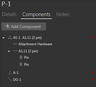
Components
The Components tab lets you view, add, edit, or delete equipment connected to the pole. You can add Assemblies, Equipment, Guys, and Anchors.
Notes
The Notes tab allows you to attach, view, modify, or delete notes and images for a pole. When you create a snapshot of a pole using the Snapshot tool  in the 3D View, the image is appended in the pole's Notes section.
Click the Add Image icon to browse your local storage for an image file to include with the selected pole. Click the Add Text icon to attach a text note to a pole. To modify text, click inside a note box.
Delete attached notes and images by clicking the red x that appears to the right of each entry when you hover your cursor over it.
Icons and Labels
OHDA uses the following icons and labels to identify each component in the list.
| Component | Icon | Label |
| Assembly |  |
AS-n + Component name |
| Attachment Hardware |  |
Component name |
| Cross Arm |  |
Component name |
| Insulator |  |
Component name |
| Cylinder |  |
T-n |
| Cube |  |
S-n |
| Guy |  |
DG-n |
| Anchor |  |
A-n |
| n begins with 1 and is incremented by 1 for each additional component of the same type. |