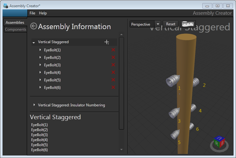
Follow these steps to add a vertical brackets to an assembly:
- Click the plus (+) symbol next to the inline assembly name.
- Select Vertical Bracket from the drop-down menu. This option is only available when no attachment hardware, cross arms, or other vertical brackets exist on the assembly.
- Select the Bracket Spec from the drop-down list. This list is populated with any eye bolts, braced brackets, or stand off brackets created in Assembly Creator. Refer to the Bracket Hardware topic for information on creating these brackets.
- Select the Insulator Spec from the drop-down list. The list is populated with any valid insulators for the bracket type created in Assembly Creator. Each time the value of the list changes, the canvas will display the current selection. Refer to the Insulator topic in this guide for information on creating these components.

Eye bolts can only accept suspension insulators. Stand off brackets can accept pin, post, and suspension insulators. Braced brackets will accept any type of insulator.
- Set the number of brackets to place on the assembly in the Bracket Quantity field.
- Set the vertical distance between brackets in the Distance Between Brackets field.
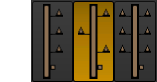
- Select Vertical, Staggered, or Paired by clicking the appropriate icon.
Edit Component
|
Double-clicking an individual vertical bracket will open its edit form where you can adjust that component's attributes. You will be able to adjust name, specs, bracket quantity, distance between brackets, and position. |
Name - An editable field that allows you to name the component. It automatically defaults to the type of component selected, with a number in parenthesis if there are more than one of this type of component.
Bracket Spec - Select the bracket spec from the pulldown list.
Insulator Spec - Select the insulator spec from the pulldown list.
Upper Level - Shows the user exactly which component the Distance From Upper Level value is referencing. This field cannot be edited by the user.
Distance From Upper Level - An editable value that allows the user to position the bracket. Editing the value for Distance From Upper Level will move the bracket in reference to the component directly above it, and update it's position in the corresponding 3D View. If the value is set to be large enough that the component being edited leapfrogs to a position below the next lowest component, the new Upper Level field updates immediately to show the new nearest component above it on the pole. The value for Distance From Upper Level is also automatically changed to a value that accurately references this new component. The bracket's position should be exactly where the user intended, only the Distance From Upper Level value and Upper Level component will change.
|
Because Assembly Creator does not model the exact physical specifications of brackets, the Overhead Design Analysis (OHDA) tool will not calculate transverse wind loads on the equipment. |