To edit or create new pole assemblies, direct modification of XML files is unnecessary. Instead, you can use the Assembly Creator tool that is included with OHDA in Designer.
To run the tool, navigate to the Bin folder of your ArcFM Solution installation directory and double-click the Assembly Creator.exe file.
 |
Windows users: A feature in recent versions of Windows, User Account Control (UAC), may silently prevent access to some functionality in Assembly Creator. To prevent this, you will need to right-click the .exe file and select Run as Administrator. |
Menu Options
Save
Saves your assemblies for use in OHDA scenarios. You will not need to select a save location. Your initial save will create several subdirectories in your ArcFM Solution\Bin directory:
- BoltSpecs
- Brackets
- CrossArmSpecs
- CubeAssemblies
- CylinderAssemblies
- InsulatorAssemblies
- PoleTopAssembies
Exit
Closes the program. You will be prompted to save any unsaved changes.
Help
About
Displays versioning information for the application.
View Help
Opens the help file you are now reading.
Tabs
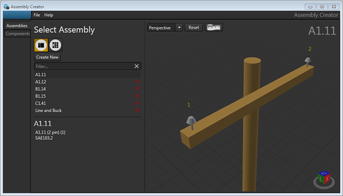
Assemblies
Combine components to create assemblies. This tab is the default view when you open Assembly Creator.
Components
Create pole attachment hardware, cross arms, cubes (representing switches), cylinders (representing transformers), and pins or insulators.
Settings
Set the Units of Measurement and the Assembly Library Location.
Views
Single View

Displays the one assembly you have selected in the assembly list in the preview window.
Catalog View

Displays all assemblies in a grid of tiles in the display window. Click an assembly in the list to highlight its tile. Double-click the assembly in the list or its tile to target it on the Assembly Information form.
 |
You can hover the cursor over a tile to interact with its view through zoom, rotation, and pan. Double-click the Catalog View icon to reset views for each tile. |
Tape Measure Tool
You can use the tape measure tool to measure distances in the 3D canvas:
- Click the
 tape measure icon. The icon's background turns orange.
 - Click on the 3D canvas. The pointer will snap to nearby features.
- Click again to measure the distance between the two points. A popup will display the distance between the two points in the units of measure you have set.
- Click the tape measure icon again to disable the tool.