Once you've launched the Create Template Favorite tool from the Features or compatible units (CUs) list, you will need to add point, span, choice, or a combination of list features. This page walks through adding a span feature to a template favorite.
- Right-click the template favorite name in the Create Template Favorite window and select Add Span.
- Drag a linear feature from the Features list or the CUs list (Designer only) and drop it onto the span you created. You may also copy and paste linear features to the template favorite.
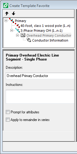
- Select the span and enter a description.
- Indicate sketch points between which the feature will appear. In the example below, a three-phase overhead conductor will begin at the first sketch point and continue to the next to last sketch point or n-1.

Template Favorite in ArcFM
|
|

Template Favorite in Designer
|
- Select the Offset tab.
- Select the Offset check box to indicate the span should be offset. Span features may be offset from the sketch line or from each other.
- In the Offset field, enter in map units the offset distance. The Offset field determines the distance that the first span is offset from the sketch line. The Increment field indicates the distance additional spans will be offset from the first span. Select the Alternate Sides checkbox to place spans on both sides of the original. In the Quantity field, enter the number of features that should be placed.
- Select from the Edge Completion options for the span's start and end types. The options in this field are described on the Edge Completion page.
- Select a Connection Style. The values in this field are described on the Connection Style page.
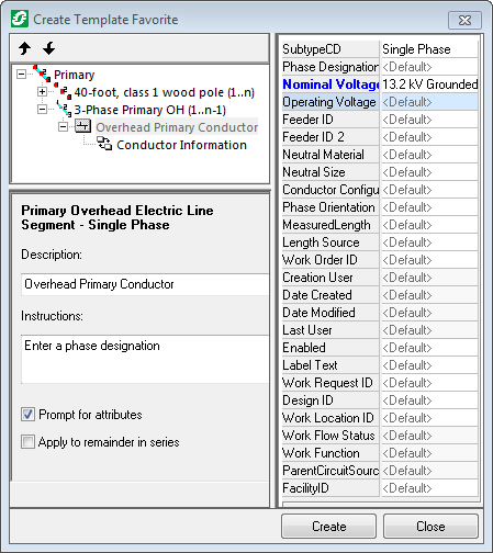
- If you're using Designer, skip to the next step. If you're using ArcFM, select the feature and edit attributes on the right side of the Create Template Favorite window. The field names for edited attributes appear in blue. If a field does not accept a null value and no value is assigned, it is highlighted in yellow.

-
Designer only. If you're using ArcFM, skip to the next step. If you're using Designer, select the feature at the GIS unit (GU) level and edit attributes on the right side of the Create Template Favorite window. If you have created the template favorite using CUs, there will be two layers to each feature. The parent level of the CU allows you to edit feature attributes. The child level of the CU allows you to view Work Management System (WMS) information. The field names for edited attributes appear in blue.

- The checkboxes at the bottom affect what happens when the user places the template favorite. You may enable any combination of these options.
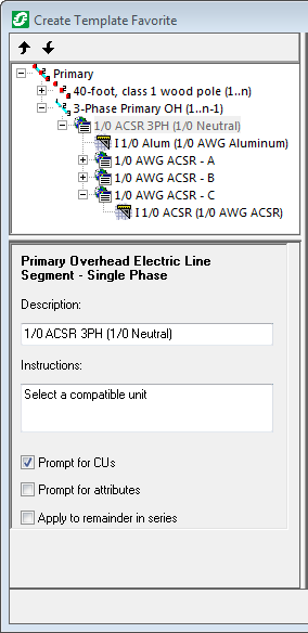
Prompt for CUs Designer only.
If this option is checked and the template favorite is placed with a design open, users will be prompted with a dialog box that allows them to change the CU while placing the template favorite. If no design is open when the template favorite is placed, the default CU will be used.
When a design is open, the user may select a CU. The GU filters the search. In the example above, the GU is a three-phase primary conductor, so the user can only select from three-phase primary conductor CUs. You may right-click the CU under the GU and select remove to force the user to select a CU. If you leave the CU under the GU it will be used as the default CU if the user doesn't select one.
This dialog also allows the user to add Non-GIS CUs or elect to apply the chosen CU to the rest of the features in the series. Prompt for CUs allows the user to select any CU in the feature class.
Prompt for attributes
If this option is checked, users will be prompted with a dialog box that allows them to modify attribute values.
 |
You may want to display these fields at the top of the attribute grid. Use the ArcFM Properties Manager in ArcCatalog to modify the order in which attributes are displayed. This will affect the order on the Attribute Editor as well. |
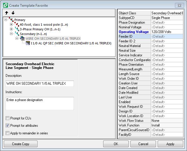
Apply to remainder in series
If this option is checked, the CU and attribute settings will be applied to all other features in the series. In the example above, the user is placing three lines of secondary. If the administrator selected this checkbox and the Prompt for attributes checkbox, the attributes the user selected for the first secondary conductor will be applied to all other conductors in the series. Apply to remainder applies to like features, CUs, or related objects within a single series only.
- Use the Instructions field to enter a description of what the user should do (select a specific type of CU, enter attribute values, etc.). The text in the Instructions field will be displayed to the user while placing the template favorite.
- Designer only. You may select the feature at the CU level and view (but not edit) general information about it. This is CU-defining information and may not be edited.
- If you have multiple point, span, and choice list features in your template favorite, use the up and down arrows
 to change the order of the point, span, and choice list features. Features will be placed in the order in which they appear in the template favorite.
- Continue to add points, spans, and choice lists as needed.
- Click Apply to accept edits, then Close to dismiss the Create Template Favorite dialog.
- Click Create to save the template favorite and dismiss the Create Template Favorite dialog. If you click Create multiple times, multiple template favorites will be created.
- Click Close to dismiss the Create Template Favorite window without saving the template favorite.


 to change the order of the point, span, and choice list features. Features will be placed in the order in which they appear in the template favorite.