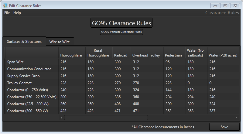
Overhead Design Analysis (OHDA) is preset with clearance rules. You have the option of using the default rules or creating your own.
Creating Clearance Rules
To use your own clearance rules instead of the defaults, follow these steps:
- Define specifications in an XML file, as detailed below.
- Name the file MinerStructuralAnalysis_ClearanceRulesSet.xml, and save it in the Assembly Library Location directory. This directory location is defined in the Assembly Creator on the Settings Tab.
 |
If a custom clearance rule file becomes corrupted, OHDA will alert the user that default rules will be used instead. |
 |
Windows users: A feature in recent versions of Windows, User Account Control (UAC), may silently prevent access to some functionality in the clearance rule editor. To prevent this, you will need to right-click the .exe file and select Run as Administrator. |
The tool has two tabs when working with vertical clearances:
Surfaces and Structures
The distance in inches that individual surfaces and structures require for clearance underneath a span.
Wire to Wire
The clearance distance in inches needed between different types of cables. Because top wires are used as a point of reference, they act as the row headings in the leftmost column of the table. |
Most radial clearance distances used in OHDA come directly from GO95 or NESC standards tables, except where very high voltages are involved. The higher-voltage clearance values are derived from formulas that round results to the nearest inch before applying them to an analysis. |

To modify clearance rules, follow these steps:
- Open the Clearance Rules.exe file in the ArcFM Solution\Bin directory.
- A dialog will open asking for a clearance rules table to modify. If you have not created a table yet, navigate to the ArcFM Solution\Bin\Xml directory. Double-click GO95ClearanceRules.xml or NESCClearanceRules.xml to open either standards-based table. Otherwise, double-click your MinerStructuralAnalysis_ClearanceRulesSet.xml file located in the Bin directory. The application will not open an invalid clearance rules XML file.
- Set data by clicking on fields and entering desired values. After any changes are made, an asterisk will appear on the Save button to alert you that unsaved information exists in the table.

Zeros in the Clearance Rules table are more accurately defined as null values. For example, in the image above, the GO95 table has a zero value for Trolley Contact over water because that condition will likely never occur. - If you want to change the order of columns during an edit session, click and hold the column's heading and drag to adjust its location in the table. The divider between column headings turns blue to indicate where the column will be placed once you release the mouse button. This can be useful to compare clearance values between columns set far apart in the table. This order will not be remembered once the tool is closed.

To permanently change the order of columns, you must edit the XML file directly. Because the first column is used as the default Base Surface Type in OHDA, this may be beneficial in rare instances. - To avoid possible confusion, click on the title field and rename the modified table. The title appears on the Rules section of the Profile tab in OHDA.
- After all desired changes are made, press the Save button.
- Navigate the save dialog to the ArcFM Solution\Bin directory.
- Name the file MinerStructuralAnalysis_ClearanceRulesSet.xml.

You must use this exact file name and location for the OHDA calculation engine to use the modified values.
- Click Save. The next time OHDA runs, the application will used the modified table of values to analyze clearance distances.
 |
OHDA uses NESC clearance specifications by default. |
