
Version: 10.2.1c and 10.2.1c SP3 |
| ArcFM Desktop Overview > Designer > Design Optimization > Optimize Secondary Circuits |
When the layout is aggregated, Design Optimization places graphics at multiple possible locations. For example, aggregation may place two service points in two locations on the same parcel. The Optimize and Complete Secondary Circuits step reviews these graphics and chooses the optimal location for each. So, it would analyze the two service points in our example and choose the best option based on the administrator-defined parameters. Optimize and Complete Secondary Circuits computes the relative cost for the design configuration. This step will not become enabled until aggregation (Group Parcels) is complete.
Click the Optimize Secondary Circuits to optimize the design layout. The Design Optimization tool will evaluate the proposed feature locations (represented by graphics) and automatically select the graphics at the optimal locations based on the administrator-defined parameters such as estimated loads, voltage drop and flicker, and the relative cost of transformers, conductors and pedestals. The relative cost of the design is computed by taking the relative cost of transformers, conductors, and pedestals into consideration for each layout. Relative cost is displayed on the bottom of the Design Optimization pane.
Accept the default selection of Not Set to accept phasing based on administrator-defined parameters or choose a specific phase designation by clicking the radio button next to the desired phase (A, B, or C). This field sets the phase on all conductors and devices in the design.
Once you've performed the optimization task, the Draw Exclusion Zones step becomes disabled.
 Remove Optimization Results
Click this button to remove the optimization results. You may want to use this tool if you want to add an exclusion zone after optimization. Remove the results, draw the exclusion zone, then execute the Optimize Secondary Circuits tool again.
 Associate Parcel to New Transformer
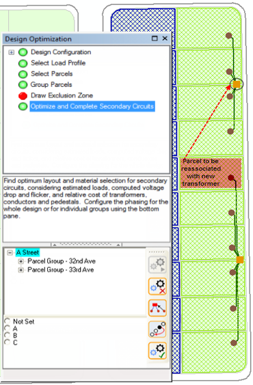
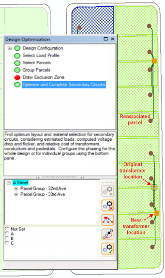
Use this tool to manually associate a parcel from one group to a transformer in a different group. Click the Associate Parcel to New Transformer button. The cursor snaps to parcels, so select the parcel you want to re-associate. Next, click the transformer to which you want to associate the parcel. Design Optimization will automatically reoptimize the secondary circuits and relocate transformers if necessary as well as update the relative cost. The following example depicts associating the highlighted parcel to a new transformer. Secondary circuits and a transformer were relocated in response to associating the parcel to a new transformer. Likewise, relative cost was updated to reflect the design's new configuration.
 |
 |
 Move Transformer or Pedestal
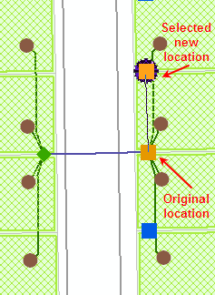
Use this tool to specify a new location for a transformer or pedestal. Click the Move Transformer or Pedestal button and then click the transformer or pedestal you would like to move. Design Optimization will display potential new location(s) for the selected object based on previously defined electric optimization and cartographic parameters. See the section entitled, Set Design Parameters for more information on optimization parameters.
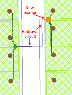
Click on a potential new transformer or pedestal location. Design Optimization will recalculate the circuit information and redraw the circuit and the new transformer location on the map. Design Optimization will also recalculate the relative cost for the design.

|

|
If the new location does not meet previously defined voltage drop and flicker requirements as defined by the design parameters, you will be asked if you want to revert back to the previous circuit. Click "No" to accept the new location you chose. The new circuit and transformer location will be drawn on the map. Click "Yes" to cancel the move.
Work Function: The work function field for all CUs is automatically set to Install.
Transformer Rotation: Upon completion, Design Optimization automatically rotates all transformer CUs to be parallel with the street.
This tool replaces the optimized graphics with compatible units based on the Administrator-defined parameters. Each Graphic favorite in the Design Optimization category must have a corresponding favorite in the currently open map. When the user completes an optimized layout, the graphics are replaced with their corresponding favorites. If a favorite is missing from the map layers during this step, you will encounter errors.
Work Function: The work function field for all CUs is automatically set to Install.
Transformer Rotation: Upon completion, Design Optimization automatically rotates all transformer CUs to be parallel with the street.