
Version: 10.2.1c and 10.2.1.c SP3 |
| Appendix > How Water Tracing Works > Water Valve Isolation |
The purpose of the Valve Isolation trace task is to identify valves that need to be operated (closed) to prevent flow of water to a particular location. Anticipated uses are to determine valves to be operated to prevent continued flow in the event of a water leak, or valves to be operated to accomplish a scheduled outage in a designated location.
Configuring networks involves assigning model names to features and fields so that ArcFM autoupdaters can maintain connectivity information in the logical network. The valve isolation traces include a feature class assigned model name NETWORKSOURCE, a feature class assigned model name VALVE with two fields assigned model names NORMALPOSITION and OPERATINGCLASSIFICATION. The value in the normal position field indicates whether the valve is normally open or closed; the value in the operating classification field indicates whether the valve is critical. And, for every network feature, a weight is assigned to a field with the model name WATERTRACEWEIGHT.
This trace considers only those valves that lie between the isolation point (the user-defined edge flag) and a water source – such as a treatment plant or pump station. Valves that lie downstream of the isolation point are not included in the results.
Trace operations
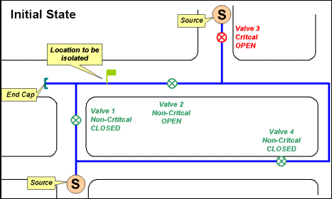
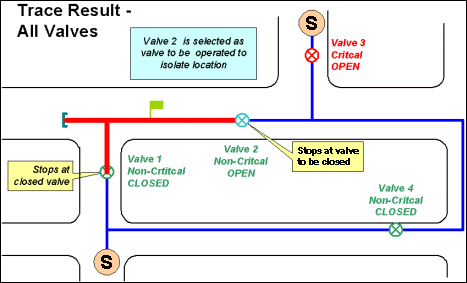
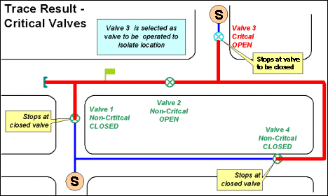
The results include the area affected if the valve is closed and the open valves (or the open critical valves) that must be operated to isolate the area. Results are displayed (highlighted) on the map or listed as the selected set, depending on the option chosen in the Results tab. Consider the following examples:
 |
 |
 |
Object Class Model Names: VALVE, NETWORKSOURCE, REGULATOR (optional), DISTRIBUTIONMAIN (optional)
|
Field Name (can be any name) |
Field Model Name (exact spelling) |
|---|---|
|
NormalPosition |
NORMALPOSITION |
|
OperatingClassification (optional) |
OPERATINGCLASSIFICATION |
|
OperatingPressure |
OPERATINGPRESSURE |
Valve Isolation Bit Interpretations