
Version: 10.2.1c and 10.2.1.c SP3 |
| Appendix > How Electric Tracing Works > Electric Trace Options |
Administrative Options – Feeder Manager Settings
The only administrative option that affects ArcFM Electric Tracing behavior for all users is the Feeder Manager’s "Use conductor phase designation" setting. This option is found in the Feeder Manager Settings dialog in ArcCatalog.
Ad Hoc Options
The user can manipulate a number of variables that affect the behavior of ArcFM Electric Tracing within the current ArcMap session, without affecting tracing behavior for other users in other sessions (see note). Some of these variables are unique to ArcFM Electric Tracing, others belong to the general set of tools in Esri’s Utility Network Analysis Extension.
Note: The exception is the Enabled field. Modifying this attribute field value will affect the tracing behavior for other users.
ArcFM Electric Trace Options
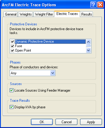
The following options appear on the Electric Traces tab of the ArcFM Electric Trace Options form (launched by the “Options…” button in the ArcFM Electric Traces toolbar). That tab also appears in the Analysis Options form associated with Esri’s Utility Network Analyst toolbar.

- Identification of circuit sources: All ArcFM Electric Tracing functions depend upon the ability to identify all junctions in the network that serve in the role of circuit source (i.e., the role of supplying power to the network). They use one of two methods to make this identification. When the option to “Locate Circuit Sources Using Feeder Manager” is chosen, any network junction feature that has a related object in the object class carrying the CIRCUITSOURCE model name will be recognized as a circuit source junction. If the option is not selected, any junction feature that (1) belongs to a feature class that was designated as a source/sink class at the time the network was built and (2) has AncillaryRole = Source will be recognized as a circuit source junction.
- Identification of protective devices: All junction feature classes bearing the PROTECTIVE model name are presented in a list in the options form, and the user can determine which of those eligible classes shall actually serve to identify protective devices by checking or unchecking the box next to each class in the list. All junctions belonging to any of the checked classes will be recognized as protective devices by the Upstream Protective Device and the Downstream Protective Device trace tasks.
- Phase Constraints: The "Phases of conductors and devices" setting allows results of ArcFM Electric Tracing to be filtered according to electrical phases.
Options in the Phases menu do not affect the Next Upstream Protective Device Trace and Isolation Protective Device Trace. These trace tasks always behave as if this menu's Any option is active (i.e., they trace all phases present on the selected feature).
Utility Network Analysis Extension Options
Of the many settings and tools in Esri’s Utility Network Analyst extension, only the following affect ArcFM Electric Tracing.
- Barriers: Most ArcFM Electric Traces observe barriers, which can be interactively placed on any arbitrary set of network junction and edge features using the barrier placement tools in Esri’s Utility Network Analyst toolbar. If a junction or an edge has a barrier, no electrical phases can pass through that junction or edge.
Only the Next Upstream Protective Device Trace and the Isolation Protective Device Trace do not respect barriers. - Enabled field: ArcFM Electric Traces observe the Enabled field values for all network feature classes. No electrical phases can pass through any edge or junction feature where Enabled = False.
- Features to Trace: In the General tab of the Analysis Options form associated with Esri’s Utility Network Analyst toolbar (the General tab also appears in the ArcFM Electric Trace Options form), the user can specify that only currently selected features (or currently unselected features) are traceable. All ArcFM Electric Traces observe the user’s choice for this setting.
- Flag and Barrier Snapping Tolerance: The Flag and Barrier Snapping Tolerance setting (found in the General tab of the ArcFM Electric Trace Options form) is observed during placement of barriers, and during placement of the ArcFM trace flag.
- Results Format: This option, found in the Results tab of the Analysis Options form, determines whether results are returned as a selection set of features or as a drawing (i.e., highlighted with a special color in the map display). When returning results as drawing, there is a further option to “Draw individual elements of complex edges.” This latter option, when chosen, is observed only by the Trace Upstream function, since it never makes a perceptible difference in any of the other electric trace tasks.
- Results Content: The option to return either “All features” or only “Features stopping the trace” is observed by the Electric Distribution Trace and by the Downstream Trace functions only, since it has no apparent use for the other electric trace tasks.
The option to return only edges, or only junctions, or both in the results is observed by all of the electric trace tasks.