Follow these steps to an add an assembly to a pole in OHDA:
- Click a pole to target for a new assembly from the list under Poles in Profile. You can also select a pole by clicking it in the Plan view.
- Click Components to access the Add Component button and list the pole's current components.
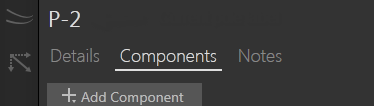
- Click Add Component.
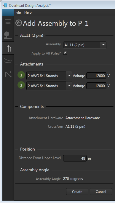
- Select Assembly from the drop-down menu. This opens the Add Assembly form.
- Select an assembly from those available in the Assembly drop-down list. Assembly types can include inline, macro, vertical, neutral bracket, or pole top bracket.

Use the keyboard to quickly navigate the list. Pressing a key will jump to the next item in the list that begins with that letter or number. 
-
When more than one set of cables dead-end on a single pole, you should create separate assemblies for each dead-end cable run.
- You cannot place more than one assembly containing a pole top bracket on a pole.
- You must place assemblies that contain a pole top bracket on a pole first before placing any assemblies that lie beneath it. This behavior includes stringing a communication cable, which you must do after placing any pole top assemblies you want to include in the scenario.
-
- Select the Apply to All Poles checkbox if you want OHDA to create the same assembly for all poles in the profile. Selecting this option will open an Attachments section where you can define the cables strung on the profile's new set of assemblies. The amount of pins on the assembly determines the number of attachments available.
- Set the Distance from Upper Level for the assembly. The upper level is either the top of the pole for top-most assemblies or the next highest assembly for poles with multiple assemblies. If the upper assembly is a cross arm, the distance is measured from that cross arm's attachment point. If it's a vertical assembly, the distance is measured from the lowest bracket in the assembly, including neutral brackets. For pole top brackets, this field has no impact on the design.
Vertical assemblies with multiple brackets are treated as a single component. The distance from upper level for multiple-bracket assemblies is measured from the top bracket. The distance from upper level value for components below the multiple-bracket assemblies are measured from the bottom-most bracket. - The Assembly Angle is automatically set based on the incoming line angle.
- Click Create. The Calculate button turns red and a refresh calculations warning message is displayed at the top of the canvas.
- Click Calculate to analyze the updated scenario. The canvas reflects the new assembly (and cables, if needed).