These instructions are for GIS Administrators who are currently in production with Fiber Manager and want to upgrade to the most recent release. These documents do NOT apply if you are not currently using Fiber Manager and will be implementing it for the first time. If you are setting up Fiber Manager for the first time, follow the steps outlined on the Overview page.
Customers upgrading from Fiber Manager 10.2.1a Patch #1156 will need to perform the following:
- Configure your geodatabase with the new circuit model (see Configure Circuit Manager for configuration steps).
- Check your data to ensure that all your circuits have header information (see the Fiber Header Migration PDF for best practices).
- If all of your circuits have header information, proceed to the next step.
- Run a patch for ArcFM Desktop Solution.
- Uninstall previous versions of Fiber Manager.
- Install Fiber Manager 10.2.1a.
- Run the ArcMap Configuration Cleaner if you previously upgraded to 10.2.1a.
- Run the Fiber Circuit Upgrade tool if existing circuits are present in your data (review the Fiber Circuit Upgrade Tool PDF for more details).
Customers upgrading from Fiber Manager 10.2.1 and earlier will need to perform the following:
- Check your data to ensure that all your circuits have header information (see theFiber Header Migration PDF for best practices).
- If all of your circuits have header information, proceed to the next step.
- UpgradeArcFM Solution Desktop to 10.2.1a.
- Run a patch for ArcFM Solution Desktop.
- Install Fiber Manager 10.2.1a.
- Configure your geodatabase with the new circuit model (see Configure Circuit Manager for configuration steps).
- Run the Fiber Circuit Upgrade tool if existing circuits are present in your data (review the Fiber Circuit Upgrade Tool PDF for more details).
 |
Part of upgrading Fiber Manager involves making your geodatabase compatible with the flexible fiber data model. You have to perform this conversion only once.
|
These steps walk you through upgrading schematics in a 9.x geodatabase for use with 10.x versions. This includes 10.0.1 and later releases.
Flexible Geodatabase
This version supports a flexible fiber data model which allows you to easily add features to your fiber data set and configure them to participate in your fiber network. If you would like to take advantage of this functionality, follow the steps outlined in the Configure Flexible Features section.
Prepare Circuit Schematics for Upgrade
Note that these steps are performed BEFORE upgrading the geodatabase.
Follow the steps below to upgrade your circuit schematics for use with 10.x versions. In these steps you'll need to identify element types that do not exist in the database. If anything in the Element Types list does not exist in the database, you will experience errors during the migration to 10.x versions.
 |
DO NOT DELETE ELEMENT TYPES. This will cause the migration to fail. The steps below walk you through disassociating these elements with the schematics.
|
- In the 9.3.1 (or 9.3.1 SP1) version of ArcCatalog, right-click the CircuitSchematics dataset and select Edit Project.
 |
If Edit Project is disabled, ensure you have the Schematics extension checked out. Select Tools > Extensions from the main menu and select the checkbox next to Schematics.
|
- In the CircuitSchematics project window, expand Element Types in the left column.
- Look for any element types that do not exist in the geodatabase. Typically the element types in all caps are table names and the rest are alias names. For example in the sample Minerville.mdb, ENDDEVICEPORT appears in the Element Types list, but no table in the geodatabase has this as its name or alias. The next steps walk through how to disassociate element types like this from the fiber circuit diagram. DO NOT DELETE NOR REMOVE THESE ELEMENT TYPES.
- Right-click an element type and select Edit Associations.
- Unselect the checkbox next to FiberCircuitDiagram.
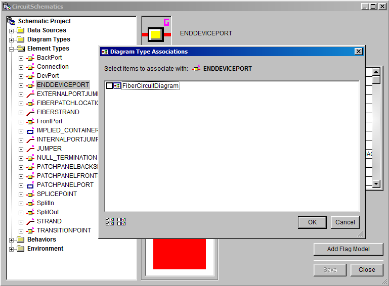
- Click OK.
- Perform steps 4-6 for each element type that does not exist as a table name or alias name in the geodatabase.
- In the CircuitSchematics project window, click Save. When prompted click Yes to confirm the save.
- Click Close.
- Close the ArcGIS Schematics Designer.
Now you can upgrade the geodatabase to 10.x (i.e., run the Upgrade ArcFM Solution Database and ArcFM Solution Create System Tables tools) and perform the steps to upgrade all schematics (outlined in the next section). After these steps, you will need to upgrade Circuit Schematics (outlined in a section on this page).
Upgrade All Schematics
The 10.x versions require you to upgrade the schematics part of Fiber Manager. To upgrade, follow the steps below.
- In ArcCatalog right-click the geodatabase and select Properties.
- In the Properties window, select the General tab and click Upgrade Geodatabase.
- In the Upgrade Geodatabase window, select both Perform Pre-requisite check and Upgrade geodatabase. Click OK.
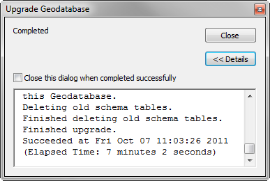
- After the geodatabase upgrade is complete, click Close.
- Click OK to dismiss the Database Properties window.
Upgrade Circuit Schematics
Now that you've prepared the CircuitSchematics dataset, upgraded the geodatabase and performed the steps to upgrade all schematics, you are ready to perform the steps necessary to upgrade the CircuitSchematics dataset to a 10.x version. Follow the steps below.
- In ArcCatalog 10.x, right-click the CircuitSchematics dataset and select Migrate to the Current Schematic Version.
- Click OK.
- In the Migrate to the Current Schematics Version screen, use the "Output Geodatabase or Schematic Dataset" field to browse to the geodatabase that will hold the upgraded dataset.
- In the "Output Schematic Dataset Name" field enter the name of the dataset. You can enter the name of the existing dataset (e.g., CircuitSchematics in the sample data) to replace it. Alternately, you can enter a new dataset name to create a new dataset that has been upgraded to 10.x (e.g., CircuitSchematics10).
- Select the radio button for "Definitions and Diagrams."
- Click OK.
- Right-click the new dataset and select Edit. If it's not visible, right-click the geodatabase and select Refresh.
- In the Schematic Dataset Editor highlight the FiberCircuitDiagram and select the Properties tab.
- In the Layout field select Geo - Spatial Dispatch. You may want to click the button next to the Layout field and set the Layout properties. However, the default settings are fine for this configuration.
- In the Schematic Builder section, ensure the XML Builder radio button is selected.
- Click the Properties button in the Schematic Builder section.
- In the Builder Properties, enter the following in the Generate and Update fields: Miner.Desktop.FiberManager.CircuitSchematic.
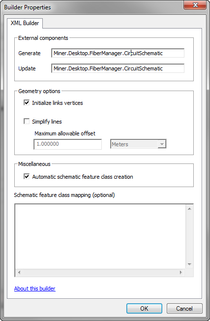
- In the Geometry Options section, select the checkbox for Initialize Links Vertices.
- In the Miscellaneous section, select the checkbox for Automatic schematic feature class creation.
- Click OK.
- In the Schematic Dataset Editor, click the Save button.
- Close the Schematic Dataset Editor and close ArcCatalog.
- Open ArcMap and select a stored display with Fiber data (or somehow populate the map with Fiber data) . In the next few steps, you'll set the symbology for all schematics created by any users.
- Next, you'll generate a schematic and set the symbology.
- Click the Generate Schematic button on the Schematic toolbar.
- In the Schematic Dataset or Folder field, select the Schematic Dataset you just created.
- Select FiberCircuitDiagram from the Schematic Diagram Template field.
- Set the Output Data Frame field to Layers.
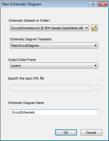
- Provide a name for the schematic in the Schematic Diagram Name field. Click OK.
- You will be prompted to select a circuit to export. Choose one and click Export.
- In ArcMap, look for CircuitSchematic in the TOC. Here you can edit the symbology for the schematic.
- Once you've finished editing the symbology, right-click the CircuitSchematic layer and select Save As Layer File. You'll import this layer in a later step.
- Close ArcMap and reopen ArcCatalog.
- In ArcCatalog, right-click the current CircuitSchematics dataset and select Edit.
- In the Schematic Dataset Editor, right-click FiberCircuitDiagram and select Import Default Symbology.
- Import the layer file you created in step 27.
- In the Schematic Dataset Editor, click the Save button.
- Close the Schematic Dataset Editor and close ArcCatalog.
Upgrade Splice Schematics
The 10.x versions require you to upgrade the schematics part of Fiber Manager. To upgrade, follow the steps below. You cannot upgrade an existing schematic dataset. Rather you will create a new dataset for the new version and import the existing dataset into it.
- This configuration requires access to the SpliceButterflyDiagramLayerTemplate.lyr layer file. This file must reside in a directory to which ArcCatalog has access.
- If you use a 32-bit version of Windows 7, copy this file from: C:\Program Files\Miner and Miner\ArcFM Solution\Support.
- If you use a 64-bit version of Windows 7, copy this file from: C:\Program Files (x86)\Miner and Miner\ArcFM Solution\Support.
Paste it into a directory that also appears in the Folder Connections list in ArcCatalog.
- In ArcCatalog, select Customize > Extensions and ensure the Schematics extension is selected. Click Close.
- Right-click the SpliceSchematics dataset and select Migrate to the current Schematic version.
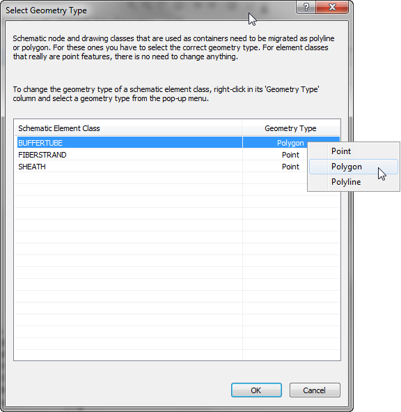
- In the Select Geometry Type window, right-click the Geometry Type for BUFFERTUBE and change it from point to polygon. Click OK.
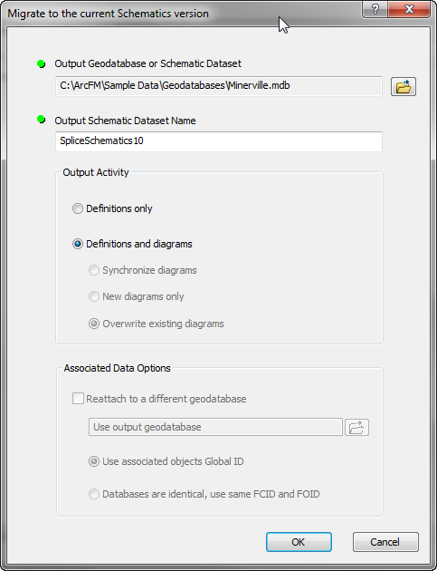
- In the next window, select the Browse button next to the Output Geodatabase or Schematic Dataset field and browse to the geodatabase in which you want to create a new (upgraded) schematics dataset. When upgrading, this will likely be the same geodatabase that contains your current schematics dataset.
- In the Output Schematic Dataset Name enter the name of the new dataset to be created (SpliceSchematics10 in the example). This is the dataset into which your existing dataset will be imported.
- Select the Definitions and Diagrams radio button and click OK to begin migrating data from your existing dataset into the new one.
- Click Close when the migration is complete.
- In ArcCatalog, right-click the new dataset (SpliceSchematics10 in the example above) and select Edit. If it's not visible, right-click the geodatabase and select Refresh.
- In the Schematic Dataset Editor highlight the FiberSpliceDiagram and select the Properties tab on the right.
- In the Layout field select Splice Butterfly Diagram. Accept the default settings in the Layout Properties dialog (visible if you click the button next to the Layout field).
- In the Schematic Builder section, ensure the XML Builder radio button is selected.
- Click the Properties button in the Schematic Builder section.
- In the Builder Properties, enter the following in the Generate and Update fields: Miner.Desktop.FiberManager.SpliceSchematic.
- In the Geometry Options section, unselect the checkbox for Initialize Links Vertices.
- In the Miscellaneous section, select the checkbox for Automatic schematic feature class creation.
- Click OK.
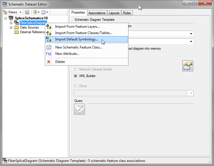
- In the Schematics Dataset Editor right-click FiberSpliceDiagram and select Import Default Symbology. Browse to the layer file provided with the ArcFM Desktop installation: SpliceButterflyDiagramLayerTemplate.lyr. This layer file resides in the location used in step 1. Click Open.
- In the Schematic Dataset Editor, click the Save button.
- Close the Schematic Dataset Editor and close ArcCatalog.
- In ArcMap, open a stored display that contains fiber data (or somehow add fiber data to the map).
- Click the Generate Schematic button on the Schematic toolbar.
- In the Schematic Dataset or Folder field, select the Schematic Dataset you just created (e.g., SpliceSchematics10).
- Select FiberSpliceDiagram from the Schematic Diagram Template field.
- Set the Output Data Frame field to [Create New Data Frame].
- Enter a name for the schematic in the Schematic Diagram Name field. Click OK.
- When prompted choose a splice to export and click Export. the schematic will be displayed in a new dataset.
- On the Schematic toolbar, select Schematic > Save Diagram As. This allows you to save the splice schematic diagram.
- Close ArcMap and open ArcCatalog.
- In ArcCatalog, right-click the schematic dataset (SpliceSchematics10 in the example), and select Edit.
- Expand FiberSpliceDiagram. In these next steps, you'll add three attributes, if they don't already exist. Perform steps 32-33 for each of the following fields.
|
Name
|
Type
|
Value
|
Predefined
|
Evaluation Mode
|
| ContainerMargin |
Constant |
0.5 |
Checked |
On Generate/Update |
| ContainerMarginSymbolsFlag |
Constant |
0 |
Checked |
On Generate/Update |
| ContainerMarginUnit |
Constant |
1 |
Checked |
On Generate/Update |
- Right-click BufferTube and select New Attribute.
- Set the properties as shown in the table above and click OK.
- Click Save in the Schematic Dataset Editor.
- Close the Schematic Dataset Editor and close ArcCatalog.
Set database permissions
To make the new schematic dataset visible to users, you must set database permissions accordingly.


