The following sections describe the procedure you must follow to create the schematics dataset necessary for circuit schematics, how to create the initial circuit schematic, and how to define default symbology for all circuit schematics created by any user.
 |
Only the owner of the database can create a schematic dataset. After the creation of an initial schematic dataset, any user with DBO permissions can create a schematic dataset for circuit and splice schematics, or run the Fiber Trace Schematic Configuration tool. Once a circuit schematic dataset exists, a specific user must use ArcMap to generate the first circuit schematic. This user must not only be the owner of the circuit schematic dataset, but also have DBA permissions on the database. Only then can any user with Add, Delete, or Modify permissions generate circuit schematic diagrams in ArcMap.
|
Create a circuit schematic dataset
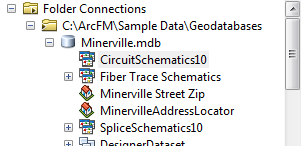
- In ArcCatalog, navigate to the Minerville sample geodatabase.
- Expand the Minerville geodatabase and locate the CircuitSchematics10 dataset.
- Right click the CircuitSchematics10 dataset and select Export > To Geodatabase. The Export Schematic Dataset to Geodatabase window appears:

- Click the folder icon to the right of the Output Geodatabase or Schematic Dataset field:

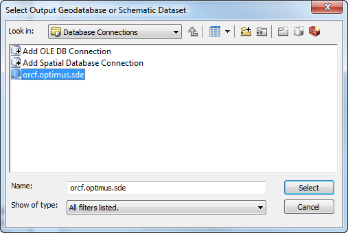
- The Select Output Geodatabase or Schematic Dataset window appears. Click a geodatabase and click Select:
- Login as the owner of the Fiber dataset.
- Type the name of the new circuit schematic dataset in the Output Schematic Dataset Name field.
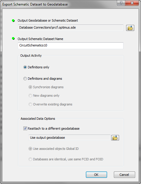
- Make sure the Definitions only radio button is selected under the Output Activity section.
- Check the box for Reattach to a different geodatabase.
- Click OK. Log into the database again if necessary. The export process begins:
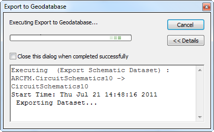
- Click Close after the export process has completed.
- Right click the new dataset (CircuitSchematics10 in the example above) and select Edit. If it's not visible, right-click the geodatabase and select Refresh.
- If necessary, log into the database again.
- In the Schematic Dataset Editor, click FiberCircuitDiagram in the left pane. Click the Properties tab in the right pane.
- In the Layout field select Geo - Spatial Dispatch.
- In the Schematic Builder section, ensure the XML Builder radio button is selected.
- Click Schematic Builder Properties
 in the Schematic Builder section.
- In the Builder Properties window, enter the following in the Generate and Update fields: Miner.Desktop.FiberManager.CircuitSchematic:
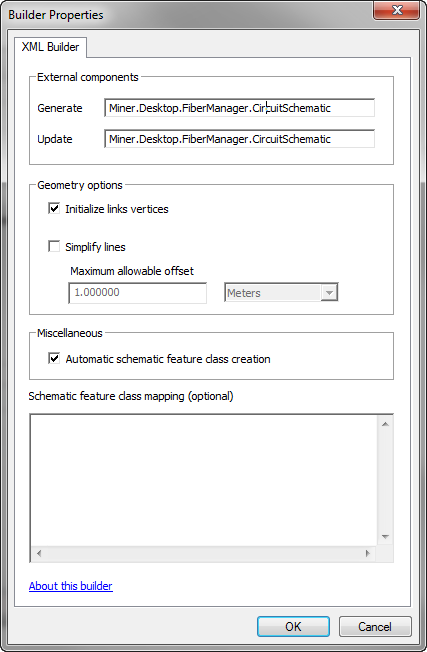
- In the Geometry Options section, check the Initialize links vertices box.
- In the Miscellaneous section, check the Automatic schematic feature class creation box.
- Click OK.
- In the Schematic Dataset Editor, click Save
 .
.
- Close the Schematic Dataset Editor and close ArcCatalog.
Set database permissions
To make the new schematic dataset visible to users, you must set database permissions accordingly.
Create the first circuit schematic diagram
Once a circuit schematic dataset exists, a specific user must use ArcMap to generate the first circuit schematic diagram. This user must not only be the owner of the circuit schematic dataset, but also have DBA permissions on the database. This is essential because only users with DBA permissions can automatically create the necessary objects and features in the schematic dataset. Only afterward can any user with Add, Delete, or Modify permissions generate circuit schematic diagrams in ArcMap.
When generating the first circuit schematic, be sure to create one that contains at least one of each feature class and related object that users will include in their circuit schematics. If these objects do not exist when a non-DBA user attempts to create a circuit schematic, schematic generation will fail.
View the Using Guide topic titled Circuit Schematics for information about creating a schematic diagram in ArcMap.
Define default symbology
 |
To see the same symbology as supplied in the sample data, you must configure Alias names to match those in the sample data.
|
- Open ArcMap.
- Generate a circuit schematic and set the symbology. For more information about generating schematics, refer to the help topics under Using ArcFM Solution Overview > ArcFM Desktop Overview > Fiber Manager > Fiber Manager Schematics.
- Save this schematic as a layer file:
- In the Table of Contents tab, right click the schematic's layer name and select Save As Layer File.
- In the Save Layer window, find a location for the new file, name it and click Save.
- Close ArcMap and open ArcCatalog.
- In ArcCatalog, right click the schematic dataset and select Edit.
- In the Schematic Dataset Editor, right click FiberCircuitDiagram and select Import Default Symbology.
- Navigate to the layer file you created in step 3. Click Open.
- In the Schematic Dataset Editor, click Save
 .
.
- Close the Schematic Dataset Editor and close ArcCatalog.


 in the Schematic Builder section.
 .
.
 .
.