You can configure Fiber Manager for use with ArcGIS Schematics. The sections below describe the steps necessary to configure Fiber Manager to display fiber trace schematics and define their default symbology.
 |
- Only database administrators can use this tool. Non-administrators will receive a permissions error.
- Do not create more than one schematic dataset for Fiber Trace Schematics.
|
Configure fiber trace schematics
Until you complete the following steps, users who attempt to create fiber trace schematics in ArcFM will receive an error.
- Open ArcCatalog.
- Click to select the database for which you want to configure fiber trace schematics.
- Click Customize > Toolbars > ArcFM Solution to display the ArcFM Solution toolbar.
- Click Fiber Trace Schematic Configuration
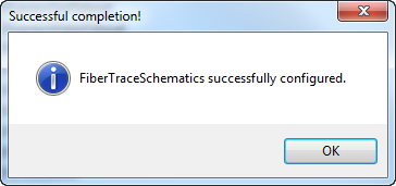
 on the ArcFM Solution toolbar. You should receive this confirmation dialog:

 |
If you do not receive this confirmation dialog, check the Windows Event Viewer. Check your Oracle database table space permissions if you see an error resembling the following: "Error: Underlying DBMS error [ORA-01950: no privileges on tablespace 'SDE_IX'', you need to check your table space permissions in Oracle 11g to specifically apply the UNLIMITED TABLESPACE permission to the SDE user." |
Set database permissions
To make the new schematic dataset visible to users, you must set database permissions accordingly.
Define default symbology
- Open ArcMap.
- Generate a fiber trace schematic and set the symbology. For more information about generating schematics, refer to the help topics under Using ArcFM Solution Overview > ArcFM Desktop Overview > Fiber Manager > Fiber Manager Schematics.
- Save this schematic as a layer file:
- In the Table of Contents tab, right click the schematic's layer name and select Save As Layer File.
- In the Save Layer window, find a location for the new file, name it and click Save.
- Close ArcMap and open ArcCatalog.
- In ArcCatalog, right click the FiberTraceSchematics dataset and select Edit.
- In the Schematic Dataset Editor, right click FiberTraceSchematic and select Import Default Symbology.
- Navigate to the layer file you created in step 3. Click Open.
- In the Schematic Dataset Editor, click Save
 .
.
- Close the Schematic Dataset Editor and close ArcCatalog.
 |
Known issue with ArcGIS 10 SP3
If users cannot generate schematics, check their Event Viewers for messages regarding long identifiers. Use the following method to work around this issue:
- Right-click the new Fiber Trace Schematic Dataset in ArcCatalog and select Edit.
- On the dataset's Properties tab, select Geo - Spatial Dispatch from the Layout drop-down menu.
- Click the Layout Properties
 button (to the right of the Layout drop-down menu). button (to the right of the Layout drop-down menu).
- Enter non-zero values for the Number of iterations and Maximum shift factor fields (e.g., 1 and 0.5, repectively).
- Click OK.
- Click Save
 . User can now generate Fiber Trace Schematics. . User can now generate Fiber Trace Schematics.
|


 on the ArcFM Solution toolbar. You should receive this confirmation dialog:

 .
.