The following sections describe the procedure you must follow to create the schematics dataset necessary for splice schematics, how to create the initial splice schematic, and how to define default symbology for all splice schematics created by any user.
 |
Only the owner of the database can create a schematic dataset. After the creation of an initial schematic dataset, any user with DBO permissions can create a schematic dataset for circuit and splice schematics, or run the Fiber Trace Schematic Configuration tool. Once a splice schematic dataset exists, a specific user must use ArcMap to generate the first splice schematic. This user must not only be the owner of the splice schematic dataset, but also have DBA permissions on the database. Only then can any user with Add, Delete, or Modify permissions generate splice schematic diagrams in ArcMap.
|
Create a splice schematic dataset
- In ArcCatalog, navigate to the Minerville sample geodatabase.
- Expand the Minerville geodatabase and locate the SpliceSchematics10 dataset.
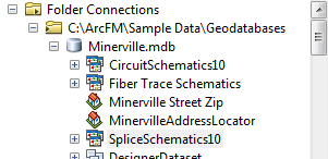
- Right click the SpliceSchematics10 dataset and select Export > To Geodatabase.
- The Export Schematic Dataset to Geodatabase window appears:

- Click the folder icon to the right of the Output Geodatabase or Schematic Dataset field:

- The Select Output Geodatabase or Schematic Dataset window appears. Click a geodatabase and click Select:
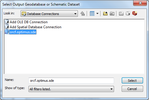
- Login as the owner of the Fiber dataset.
- Type the name of the new splice schematic dataset in the Output Schematic Dataset Name field.
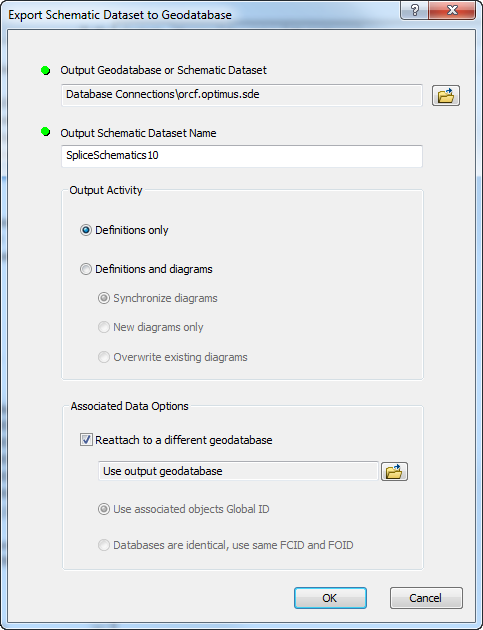
- Select the Definitions Only radio button under the Output Activity section.
- Check the Reattach to a different geodatabase box in the Associated Data Options section.
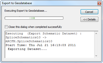
- Click OK. The export process begins:
 |
You may have to login as the owner of the Fiber dataset again.
|
- Click Close after the export process has completed.
- Right click the new dataset (SpliceSchematics10 in the example above) and select Edit. If it's not visible, right-click the geodatabase and select Refresh.
- In the Schematic Dataset Editor, click FiberSpliceDiagram in the left pane. Click the Properties tab in the right pane.
- In the Layout field select Splice Butterfly Diagram. You may want to click the Layout Properties button
 next to the Layout field. However, the default settings will work for this configuration.
- In the Schematic Builder section, ensure the XML Builder radio button is selected.
- Click Schematic Builder Properties
 in the Schematic Builder section.
- In the Builder Properties window, enter the following in the Generate and Update fields: Miner.Desktop.FiberManager.SpliceSchematic:
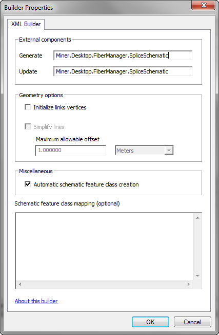
- In the Geometry Options section, clear the Initialize links vertices box.
- In the Miscellaneous section, check the Automatic schematic feature class creation box.
- Click OK.
- In the Schematic Dataset Editor, click Save
 .
.
- Close the Schematic Dataset Editor and close ArcCatalog.
- Open ArcMap and log in to the database with the new fiber splice schematic dataset. You must log in as the owner of the Fiber dataset. For permission information, refer to the Create the first splice schematic diagram section below.
- Load your fiber data (Stored Display).
- Click Generate New Schematic Diagram
 on the Schematic toolbar. The New Schematic Diagram window appears.
- Select the newly imported schematic dataset from the Schematic Dataset or Folder drop-down menu.
- Select Create New Data Frame in the Output Data Frame field.
- Name the new splice schematic diagram in the Schematic Diagram Name field.
- Click OK.
- Click a splice in Splice Export Form window. Splice points are listed by their object ID number:
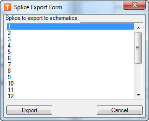
- Click Export. The splice schematic diagram appears in the ArcMap window upon the completion of the export process.

- Close ArcMap.
- Open ArcCatalog.
- In ArcCatalog, right click the dataset (SpliceSchematics10 in the example) and select Edit.
- Expand FiberSpliceDiagram. In the next steps, add three attributes if they do not already exist. Perform each of the following steps for the fields listed below:
- Right-click BufferTube and select New Attribute.
- Set the properties as shown in the table above and click OK.
- Click Save
 in the Schematic Dataset Editor.
| Name |
Type |
Value |
Predefined |
Evaluation Mode |
| ContainerMargin |
Constant |
0.5 |
Checked |
On Generate/Update |
| ContainerMarginSymbolsFlag |
Constant |
0 |
Checked |
On Generate/Update |
| ContainerMarginUnit |
Constant |
1 |
Checked |
On Generate/Update |
- Close the Schematic Dataset Editor and close ArcCatalog.
Refer to the ArcGIS help for instructions on further customizing the display of the schematic.
Set database permissions
To make the new schematic dataset visible to users, you must set database permissions accordingly.
Create the first splice schematic diagram
Once a splice schematic dataset exists, a specific user must use ArcMap to generate the first splice schematic diagram. This user must not only be the owner of the splice schematic dataset, but also have DBA permissions on the database. This is essential because only users with DBA permissions can automatically create the necessary objects and features in the schematic dataset. Only afterward can any user with Add, Delete, or Modify permissions generate splice schematic diagrams in ArcMap.
When generating the first splice schematic, be sure to create one that contains at least one of each feature class and related object that users will include in their splice schematics. If these objects do not exist when a non-DBA user attempts to create a splice schematic, schematic generation will fail.
View the Using Guide topic titled Splice Schematics for information about creating a schematic diagram in ArcMap.
Define default symbology
- Open ArcMap.
- Generate a splice schematic and set the symbology. For more information about generating schematics, refer to the help topics under Using ArcFM Solution Overview > ArcFM Desktop Overview > Fiber Manager > Fiber Manager Schematics.
- Save this schematic as a layer file:
- In the Table of Contents tab, right click the schematic's layer name and select Save As Layer File.
- In the Save Layer window, find a location for the new file, name it and click Save.
- Close ArcMap and open ArcCatalog.
- In ArcCatalog, right click the schematic dataset and select Edit.
- In the Schematic Dataset Editor, right click FiberSpliceDiagram and select Import Default Symbology.
- Navigate to the layer file you created in step 3. Click Open.
- In the Schematic Dataset Editor, click Save
 .
.
- Close the Schematic Dataset Editor and close ArcCatalog.


 next to the Layout field. However, the default settings will work for this configuration.
 in the Schematic Builder section.
 .
. on the Schematic toolbar. The New Schematic Diagram window appears.
 in the Schematic Dataset Editor.
 .
.