Create the geometric network at the dataset level. Any map documents referring to the geodatabase must be closed before the geometric network can be created.
Build Geometric Network Wizard
- Right-click the Fiber dataset created.
- Select New > Geometric Network to display the Build Geometric Network Wizard.
- In the first dialog box, click Next to start the wizard.
- Type Fiber_Network for the name of the geometric network, or give it a different name that makes sense for your business.
- Select Yes since you want the features to snap, and you want features to snap within a snapping tolerance.
- The default value is based on the XY tolerance of the feature dataset.
- For more information about snapping, see the Set Snapping Properties topic.
- Click Next.
- Select feature classes you want to participate in the network. If you are using the classic data model, you would include the features listed below. You may wish to include additional classes in your network.
- DevicePoint
- FiberFault
- FiberOpticCable
- FiberSlackLoop
- FiberStructure
- PatchLocation
- SplicePoint
- SplitterLocation
- TransitionPoint
- Click OK.
- If prompted, select whether you wish to preserve existing enabled values. The default is Yes. Click Next.
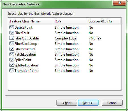
- The next dialog box shows the role assigned to each feature class. Fiber Manager requires that all point features have a role of Simple Junction and all line features have a role of Complex Edge. By default the linear features are set to Simple Edge. You will need to change this to Complex Edge.

- The next dialog box allows you to add weights. Your network does not use weights, so add nothing in this dialog box. Click Next.
- After checking the summary of your input, click Finish.
Build Errors
When the wizard has finished building your network, search your database for a table with a name containing _BUILDERR. If no such table exists, then there are no problems with your new network. If the table does exist, consult the Esri documentation regarding build errors to learn the significance of its contents and take any necessary measures to eliminate the problems it indicates. After eliminating the causes of any network build errors, you must delete the network (and the build errors table) and build again until you get no build errors.
Set the Geometric Network Properties
To open the Geometric Network Properties tool, right-click the fiber network and select Properties. The tool has a General tab, Connectivity tab, and a Weights tab. Use them to set the fiber network's properties. For more information, see the Esri documentation.


