Using ArcFM Solution Desktop
Classic Patch Panel Connection Report

Version: 10.2.1c and 10.2.1c SP3

Resource Center Home

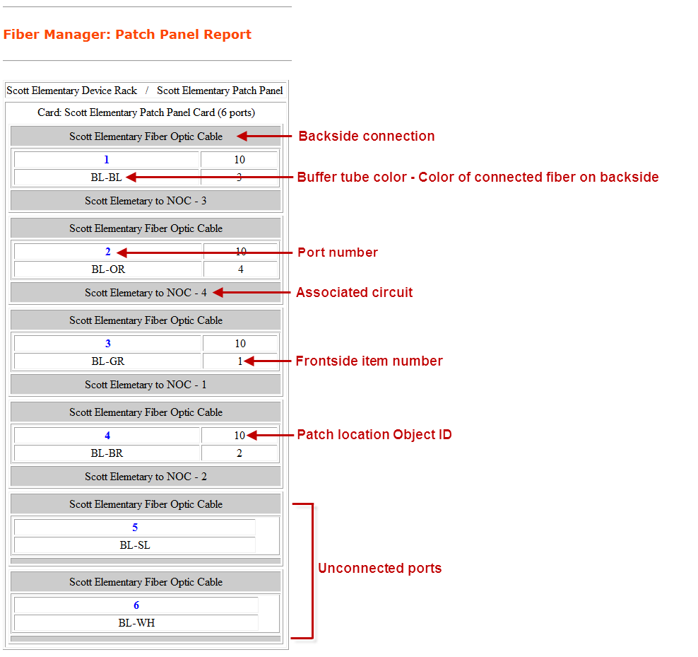
A patch panel connection report is a graphical display of the layout of a patch panel or a series of patch panels. This topic describes the patch panel connection report generated by Fiber Manager when a classic data model is being used.

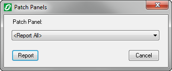
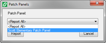
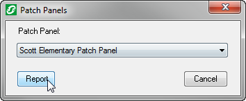
After clicking the Patch Panel Connection Report button and using the flag cursor to select the patch location (steps covered in the Patch Panel Report topic), follow the steps below.

  1.  The Patch Panels window will appear.


  2. Use the drop down menu to select a single patch panel or select <Report All> to report on all patch panels (if more than one patch panel exists at the location).

  3. Click the Report Button to run the report.

  4. A report in XML format will appear in your Web browser with a format similar to the following example. The report displays the name of any associated patch panels or device racks in the upper right corner. Connection and circuit information are displayed for each port. In the following example, the Scott Elementary Patch Panel card contains six ports.  According to the report, we can see that port number 1 is connected to a 4 port media converter and the Scott Elementary fiber optic cable which contains fiber number 1 (a blue fiber in a blue buffer tube). From the report, we can also see that the fiber in port number 1 is associated with the "School Circuit 1" circuit. Port 5 and 6 are open ports. In other words, they have no connections. 
    If the report looks different than the screenshot below, please go to the Flexible Patch Panel Report topic.


Send Comment to ArcFMdocumentation@schneider-electric.com