
Version: 10.2.1c and 10.2.1c SP3 |
| ArcFM Desktop > Conduit Manager > Underground Facility Manager > UFM Step 8: Create Map Document |
When creating a map document in ArcMap for use with UFM, there are some steps to take in order to make the data easier to view.
Required. Several Underground Facility Manager (UFM) tools rely on a unique Facility ID. Each Underground Facility (manhole) MUST have a unique value assigned to the field that has the FACILITYID field model name assigned. If this value is not assigned, some UFM tools will not work properly.
Required. When placing conduit, it must begin and end at underground structure features (with any number of vertices between). The Conduit feature class must snap to the Underground Structure feature class.
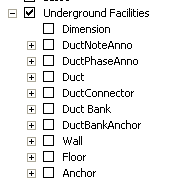
Required. The following layers must be added to the map. These layers should be turned off on the Display tab. These layers should have the UFMVISIBLE model name assigned and will be automatically displayed only when UFM displays the butterfly diagram.
Dimension
DuctNoteAnno
Duct
DuctConnector
DuctBank
DuctBankAnchor
Wall
Floor
Anchor
Required for Create Underground Facility Map Grids tool. The Create Underground Facility Map Grids tool allows you to select an underground facility with an associated facility diagram and automatically create a map grid and inset frame for it. In order to view the inset frame data in the Layout view, you will need to create a stored display that contains only UFM dataset features (see Figure 3). These features must be visible in this stored display.
Optional. You may add these layers to a separate group layer, if desired. In the example below, all UFM layers are contained within the Underground Facilities group layer.

Figure 3, UFM dataset
Optional. Because diagrams are displayed in precision editing mode (very large scale), the default line widths may appear too wide. These recommended widths and sizes make the data easier to view in precision editing mode.