
Version: 10.2.1c and 10.2.1c SP3 |
| ArcFM Desktop > Conduit Manager > Build Geometric Network |
Create the geometric network at the dataset level. Any map documents referring to the geodatabase, must be closed before the geometric network can be created.
- Right-click the Electric dataset.
- Select New | Geometric Network.
- On the first dialog box, click Next to start the wizard.
- Enter the name you want for the geometric network. Also, select whether you want snapping and the tolerance. Click Next to continue.
- Select the feature classes you wish to include in your geometric network. For Conduit Tracing, the Conduit System feature class (with model name ULS) is required and an underground junction feature class (manholes, vaults) is recommended. Click Next to continue.
- If prompted, select whether you wish to preserve existing enabled values. Click Next to continue.
- The next dialog box shows the roles assigned to the features and lets you select whether they are sources and sinks.
- In the Add weights to your network dialog box, click New. The Add New Weight dialog box opens.
- Enter Distance as the weight name and select either the single or double data type. For more information about the Distance weight, please refer to the Weights topic. Assign the Distance weight to the shape length field of the Conduit System feature class.
Default Junctions: When you create the geometric network, a default junction feature class is also created. If your map doesn't contain an underground structure feature class, the default junction layer must be added to enable Conduit Manager Find Path trace functionality (traces are allowed only between junctions).
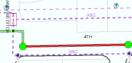
During creation of a geometric network, a default junction feature class is created (<name of geometric network>_Junctions). Default junction features are created for each edge endpoint that does not already have an existing junction feature. In the case of the underground network, it might be a manhole or vault feature. Users will place flags at the existing or default junctions to define the start and end of a conduit availability trace.

Flags (green squares in above example) are placed at the default junctions to define the start and end points of a conduit availability trace.