
Version: 10.2.1c and 10.2.1c SP3 |
| ArcFM Desktop > Conduit Manager > Conduit Manager Step 2: Create Feature and Object Classes |
The following feature classes must exist in your geodatabase for the minimum Conduit Manager configuration. If they don't exist, you will need to create them.
You may name your feature classes and fields in any way you like. The model names, however, must have the exact spelling and capitalization (model names are assigned in a later step).
 |
A geometric network (e.g., UndergroundNetwork) must include only the feature classes that represent parts of the underground structure of a conduit system. Conductors or other cables such as fiber optics should NOT be members of the underground structure network, but should be included in their own networks, such as an electric network, or a communications network. |
Conduit feature class: This feature class may be a simple or complex edge. It represents the conduit in your underground system into which cables may be placed. The Conduit feature class requires that the user create the following field with the listed data type:
|
Field Name |
Data Type |
|---|---|
|
DuctBankConfiguration |
BLOB |
|
DuctBankHeight |
long integer |
|
DuctBankWidth |
long integer |
Conductor (Cable) feature class: This linear feature class represents the underground electrical lines in your electric distribution network. For example, Minerville uses primary (PriUGElectricLineSegment) and secondary (SecUGElectricLineSegment) underground conductors in its data model. It could also represent non-electric lines such as fiber optics.
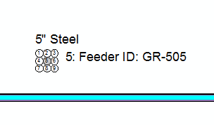
Cross Section Annotation feature class: This annotation feature class is used to display the contents of a conduit. Even if you do not wish to display annotation, this class must exist in the geodatabase (it does not have to be added to the map). You may further configure the annotation's contents list and the information displayed within it. Below is an example of cross-section annotation in ArcMap.

To create this feature class:
Duct Definition Object Class: This table defines the attributes that are stored for each duct (conduit). Any number of fields may be added to this table. For more information, see the Duct Definition help topic in the appendix: Appendix > Electric Distribution Data Model > Structures Overview > Underground Structures > Duct Definition
 |
If you are implementing GlobalIDs to support Esri Replication, note that the DuctDefinition object class does NOT support a GlobalID field. The Visibility property on this field must be set to No to avoid errors. |