
Version: 10.2.1c and 10.2.1.c SP3 |
| Appendix > Secondary Circuit Analysis Calculations > Load Flow Calculation |
This calculation determines the voltage drop of a secondary circuit. The following algorithm is used to compute the voltage at each bus (e.g., service point) and the power flow through each conductor in the circuit. All quantities are modeled by double precision complex numbers.
Load Initialization for Points Imported From ArcFM: Designer allows the user to select a feature on the map, right-click it and select Secondary Circuit Analysis. In this case, the analysis calculator determines the initial load estimate for all service points connected to the selected feature by multiplying the following values:
|
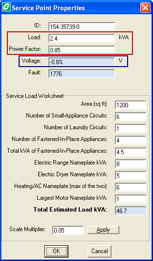
Inputs: Total apparent load Li at each service bus i. Value input on the Service Point Properties dialog (see Figure 1). Power factor PFi of the load at each service bus i. Value input on the Service Point Properties dialog (see Figure 1). Impedance Zj for each conductor segment j. This value is determined by the type of conductor selected on the Conductor Properties dialog. Transformer impedance ZXFR. This value is input on the Transformer Properties dialog. Per unit voltage Vo at the transformer primary bus (e.g., normalized to the nominal secondary circuit voltage). This value is input on the Transformer Properties dialog. Outputs: Voltage Vi at each bus i in the secondary circuit. This value may be found in the Voltage field on the Service Point Properties dialog (Figure 1). Magnitude of power |Sj| and current |Ij| flowing through each conductor j. This value may be found in the Load Power Factor field on the Conductor Properties dialog. Magnitude of total power |S| delivered to all loads on the circuit. This value may be found in the Load Power Factor field on the Transformer Properties dialog. |
 Figure 1, The Load Flow calculation utilizes the values highlighted in the red. The Voltage output is displayed in the Voltage field (highlighted in blue) |
Algorithm:

where Li is the total apparent load and PFi the power factor reported for the service, and 

where * is the complex conjugate operator.