ArcFM Desktop Developer Guide
Supported Attributes for CYMDIST Loads
In the sample implementation, load case data is stored in the geodatabase in the Transformer_Load_CYMDIST table. This table is included in the sample geodatabase installed with ArcFM Solution. You may export this table from the sample data and import it into your geodatabase. You may also create the appropriate table in your geodatabase. Below are the required fields that appear in these tables and their data types. The field names must be created exactly as shown below.
If you choose to retrieve load case data from another source, a load table is not necessary in the geodatabase.
For each load, the following attributes are required. The values for loads must conform to the domain values defined in the CYMDIST documentation. Note: Power factor percentages must be entered as whole numbers rather than decimal numbers.
|
XML Attribute |
CYMDIST Property |
Default Value |
CYMDIST Domain Values |
Description |
|---|---|---|---|---|
|
FacilityID |
facilityID |
|
|
Foreign key. Holds the Facility ID of the exported feature. |
|
LoadDate |
|
|
a date that defines a load case |
The load date associated with the exported feature. Load case data is retrieved by Load Date. When the user clicks the Get Load Case button, he is prompted to enter a Load Date. This date is used to query the load table in the geodatabase and retrieve load case data. |
|
loadstatus |
Status |
1 |
0 = off, 1 = on, 2 = disconnected, 3 = starting, 4 = looped |
|
|
loadcustomer |
ConsumerClass |
1 |
1 = residential, 2 = commercial, 3 = industrial, 4 = other |
|
|
loadlock |
Lock during load allocation |
0 |
0 = false, 1 = true |
|
|
loadconn |
Connection Configuration |
1 |
0 = Yg, 1 = Y, 2 = D, 3 = open D |
|
|
loadfrom |
power units |
1 |
0 = KW/PF, 1 = KVA/PF, 2 = KW/KVAR, 3 = AMP/PF |
|
|
loadtype |
spot or distributed |
devices: spot |
none |
Determines whether the load is added as a spot load (at one location) or as a distributed load (continuous along the conductor's length). S = Spot, D = Distributed. |
The following tables depict how you can assign loads. The Developer Sample code uses Spot Loads. You may customize your implementation to use Connected kVA or Meter Demands instead.
The CYMDIST API allows the Implementation to assign spot loads and distributed loads to both devices and conductors. If the Implementation assigns a spot load to a device, the CYMDIST API automatically assigns this load to the downstream end of the section where the device resides. Also, the Implementation can assign a spot load to a device without importing the device by using the Exclude attribute (see Supported Attributes). Note: Power factor percentages must be entered as whole numbers rather than decimal numbers.
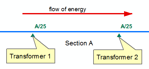
The SpotLocation field determines where on the section a spot load is placed. This field uses the cymLocation enumeration (0=from; 1=to; 2=middle). The default setting is 1.
For example, assume this topology (Section A is the portion of the conductor between the two transformers):
A value of 0 places the spot load on the left side of Section A, near Transformer 1. A value of 1 places the spot load on the right side of Section A, near Transformer 2. A value of 2 places the spot load in the middle of Section 1, equidistant from both transformers.
|
XML Attribute |
Field Name |
Data Type |
CYMDIST Property |
Recommended Value |
Description |
|---|---|---|---|---|---|
|
loadpowera |
A_kVA |
Number |
set power |
<Rated KVA |
Rated kVA on the A phase |
|
loadpowerb |
B_kVA |
Number |
set power |
<Rated KVA |
Rated kVA on the B phase |
|
loadpowerc |
C_kVA |
Number |
set power |
<Rated KVA |
Rated kVA on the C phase |
|
loadpfa |
A_PF |
Number |
SetPF or SetKVAR |
90 |
Power factor on the A phase |
|
loadpfb |
B_PF |
Number |
SetPF or SetKVAR |
90 |
Power factor on the B phase |
|
loadpfc |
C_PF |
Number |
SetPF or SetKVAR |
90 |
Power factor on the C phase |
|
spotlocation |
SpotLocation |
Number |
|
|
Determines where on the section a spot load is placed. 0 = From, 1 = To, 2 = Middle |
|
A_NumCustomers |
numcustomersa |
Number |
NbrOfCustomersA |
|
|
|
B_NumCustomers |
numcustomersb |
Number |
NbrOfCustomersB |
|
|
|
C_NumCustomers |
numcustomersc |
Number |
NbrOfCustomersC |
|
|
|
A_kWh |
kWhA |
Number |
KWHUsageA |
|
|
|
B_kWh |
kWhB |
Number |
KWHUsageB |
|
|
|
C_kWh |
kWhC |
Number |
KWHUsageC |
|
|
Rather than assigning loads directly, the Implementation can assign connected KVA for a device or conductor. After assigning connected KVAs, the Implementation can establish loads across the feeder using load allocation.
|
XML Attribute |
CYMDIST Property |
|---|---|
|
connectedkva_a |
connected KVAA |
|
connectedkva_b |
connected KVAB |
|
connectedkva_c |
connected KVAC |
Another option is for the Implementation to assign meter demands to protective devices. The CYMDIST API supports meter demands on switches, fuses, and reclosers. After assigning meter demands, the Implementation can establish loads across the feeder using load allocation.
Note: Meter demands can be set only using the IMMCymdistAPI::ApplyTestCase method, after a successful network import to CYMDIST.
Note: Power factor percentages must be entered as whole numbers rather than decimal numbers.
|
XML Attribute |
CYMDIST Property |
Recommended Value |
|---|---|---|
|
meterdemand_a |
set power - meter |
|
|
meterdemand_b |
set power - meter |
|
|
meterdemand_c |
set power - meter |
|
|
loadpfa |
set pf - meter |
90 |
|
loadpfb |
set pf - meter |
90 |
|
loadpfc |
set pf - meter |
90 |