Pole attachment hardware are the mechanisms that secure cross arms to utility poles. Assembly Creator's Components tab is where you view, create, edit, and delete attachment hardware. Select Pole Attachment Hardware in the left pane to populate the middle pane with a list of available hardware. The right pane provides details for the currently selected hardware.
 |
The results of creating, deleting, or editing components are not permanently saved until you select File > Save from the main menu. |
Create
Follow these steps to create new pole attachment hardware:
- Select the Components tab.
- Select the Pole Attachment Hardware category.
- Click the Create New button to open the Create Pole Attachment Hardware form.
- Enter the desired values for each field. The specifications are defined below.
- Click Create to add the new hardware to the component list.
Edit
Follow these steps to edit pole attachment hardware:
- Double-click the hardware you want to edit. This opens the hardware edit form.
- Enter the desired values for each field. The specifications are defined below.
- Click the appropriate button:
- Delete - delete the hardware from the hardware component list.
- Update - apply edits to the hardware.
- Cancel - exit the form without making changes to the hardware.
Delete
There are two ways to delete pole attachment hardware:
- Click the red X next to the hardware to delete in the middle pane of the Components tab.
- Double-click the hardware to open the edit form. Click Delete.
 |
An asterisks after "Assembly Creator" in the title bar denotes unsaved changes. If you close Assembly Creator without saving, a popup window will alert you that unsaved changes exist. |
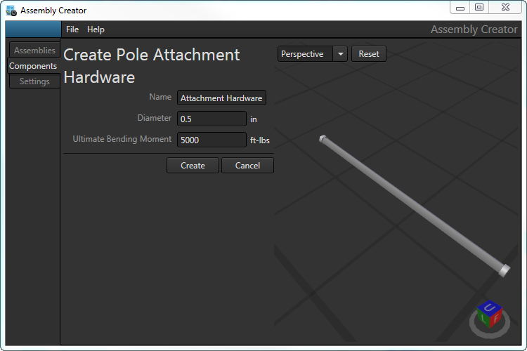
Create Pole Attachment Hardware form.
Specifications
In Assembly Creator, pole attachment hardware are defined with three parameters: Name, Diameter, and Ultimate Bending Moment.
Name
Unique identifier for the hardware. If you attempt to create attachment hardware with a name that already exists, a popup will warn of the issue when you click Create. You must provide a unique name before Assembly Creator will create the hardware.
Diameter
The diameter of the hardware at the surface of the cross arm.
Ultimate Bending Moment
The maximum amount of perpendicular load the hardware can experience before beginning to fail.
|
Any values you enter that are out of the acceptable range for that item will be outlined in red. Hover the cursor over the caution triangle to see the range of acceptable values. 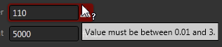
|
Attachment Hardware XML
Assembly Creator saves attachment hardware specifications for each unit in its own XML file in the Bin\BoltSpecs directory. The name of the file is the name of the attachment hardware (e.g., SAE103.2.xml).
XML Structure for Attachment Hardware
| Tag | Definition |
| <BoltSpec> | Root element. |
| <Name> | Name of the hardware. This name will display in the Assembly Creator UI. |
| <Diameter> | The diameter of the hardware in feet. |
| <MaxTensileStrength> | The maximum tensile strength of the hardware in foot-pounds (ft-lbs). In the Assembly Creator UI, the label for this value is Ultimate Resisting Moment. |
| <SpecUid> | Assembly Creator creates and records a unique id for the hardware. |
| Attachment Hardware XML Example |
Copy Code
|
|---|---|
<BoltSpec> <Name>SAE103.2</Name> <Diameter>0.0208333333333333</Diameter> <MaxTensileStrength>15000</MaxTensileStrength> <SpecUid>f1dfa0a1-ecf5-4b28-be58-b2352419bcf8</SpecUid> </BoltSpec> |
|
