The Fiber Trace tool traces a path of connectivity that was previously established with Connection Manager. The trace uses connectivity information at each junction to determine fibers' paths in both directions. This tool is useful for checking the connectivity of a light path between two points in a system. The following sections describe the process for linear tracing and point tracing.
Linear Tracing
You can trace fiber line objects with or without directional tracing enabled.
 |
- In ArcFM Viewer, whether directional tracing is enabled depends on your configuration.
- In ArcFM Solution, you can enable directional tracing in the Fiber User Settings window.
|
- Click the Fiber Trace button on the Fiber Manager toolbar
 .
.
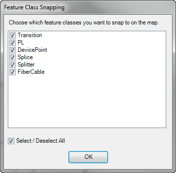
- Choose which Fiber feature classes the flag will snap to on the map. This window lists any feature with the FIBEROBJECT model name assigned (either point or line). An administrator assigns model names and determines which features are compatible with this tool. Click OK.

- If you're not using directional tracing, click a fiber cable to select it.
If you're using directional tracing, follow a two-point selection method to choose a cable and a direction:
- Click to place the flag on any fiber optic cable. A green dot indicates your selection.
- Click the cable on either side of the green dot to specify the trace direction.
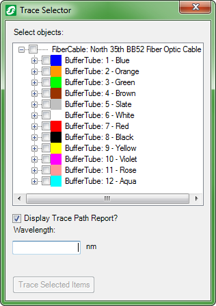
- Use the checkboxes in the Trace Selector window to select which fiber strands should be included in the trace.

- Check Display Trace Path Report if you want to view the report in a web browser.
- To trace on a specific wavelength, click in the Wavelength field and type the value (no letters nor special characters) on which to search.
- Click the Trace Selected Items button.
- Use the Zoom to Selected Features tool to display the entire trace path.
- If you checked Display Trace Path Report, view the Fiber Trace Report in your web browser.
Point Tracing
You can trace fiber point objects with or without directional tracing enabled.
 |
- In ArcFM Viewer, whether directional tracing is enabled depends on your configuration.
- In ArcFM Solution, you can enable directional tracing in the Fiber User Settings window.
|
- Click the Fiber Trace button on the Fiber Manager toolbar
 .
.
- Choose which Fiber feature classes the flag will snap to on the map. This window lists any feature with the FIBEROBJECT model name assigned (either point or line). An administrator assigns model names and determines which features are compatible with this tool. Click OK.
- Click a fiber point object.
- Use the Trace Selector to specify which fiber point objects should be included in the trace.
- Check Display Trace Path Report if you want to view the report in a web browser.
- Click Trace Selected Items.
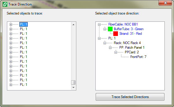
If directional tracing is enabled, the Trace Direction window appears.
- Click each of the top-level objects on the left pane.

- Use the right pane to highlight an object toward which you want to trace the object in the left pane. Blue text indicates the current trace direction.
- Click Trace Selected Directions.
- Use the Zoom to Selected Features tool to display the entire trace path.
- If you checked Display Trace Path Report, view the Fiber Trace Report in your web browser.
Details about the various types of traces (e.g., directional, linear, point) are available on the Fiber Tracing Types page in the Appendix.


 .
.
 .
.