
| ArcFM Desktop Overview > ArcFM > ArcFM Options > Phase Swap Options |
The Phase Swap options allow you to determine how the phase swap area is identified during the Phase Swap trace. The Locate Tap Point option allows you to select how the tap point is identified. The Tracing Options section allows you to determine where the trace stops. Phase swap tracing has some special cases depending on the option selected. See the Interpret Trace Results page for explanations.
These options allow you to determine how the tap point is identified. The tap point is the feature or default junction most upstream in the phase swap area and the point at which the swap is initiated. Note that your map may not include default junctions.
Automatic: When this option is selected, the Phase Swap tool identifies the tap point using two possible criteria. The tool places the tap point at the first upstream location that fits one of these criteria.
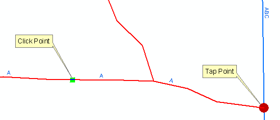
- The point at which the phase count increases. In the example below, the tap point is placed where the A phase line connects with the ABC phase line.

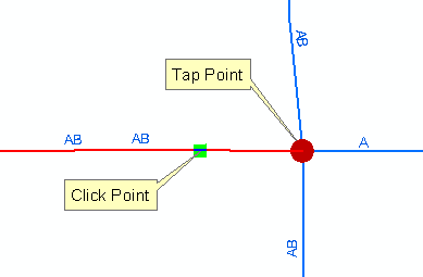
- The point at which the phase count is two or more AND the junction has more than two connected edges with the same phase designation as the conductor the user clicked. In the example below, the AB phase line highlighted in red is to be swapped. Phase Swapping identifies the tap point as the junction at which the three AB lines converge with an A phase line. The phase count is two or greater and there are more than two edges with the same phase (AB) at the junction.

Manual: This option is used generally to clean up data. It is not recommended for general use as it may create inconsistent data if not used properly.
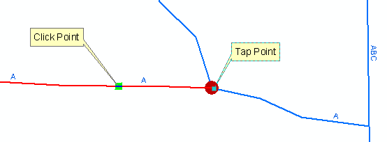
When this option is selected, Phase Swap locates the nearest upstream junction from the feature on which the flag was placed (it may locate a generic junction in the middle of the edge feature the user selected). If you place the phase swap flag on a section of primary with an A phase and the next upstream primary is also A phase, there will be no other options besides A from which to select in the phase mapping window.

With the "Manually locate tap" option selected, Phase Swap relies on the user to begin the phase swap at a location that is connected to a junction where the phase changes.
The "Disregard conductor/device phase designation" option allows you to determine how the phase swap trace identifies the end of the tracing operation.
Enabled
When the "Disregard conductor/device phase designation" checkbox is selected (enabled), the phase swap trace will continue until it encounters a device that is open on all three phases. Phase Swap updates the phases of all traced features to match the phase map selected by the user. If the phase of a feature already matches the phase selected by the user, it will not be swapped. In the example below, if the user elects to change the phase to B, all A and C phases will be swapped. The B phase line will not be modified.
Disabled
When the "Disregard conductor/device phase designation" checkbox is not selected (disabled), the phase swap trace stops when it encounters an inconsistent phase designation. In the example below, the A phase line was traced until the trace encountered the C phase line.