
| ArcFM Desktop Overview > ArcFM > Gas Traces |
Gas trace tasks allow you to check how natural gas is flowing through a network of connected features. Using the Gas Trace options, you can define protective devices and determine how sources are located. The Valve Isolation trace lets you designate valves as included or excluded as well as place temporary sources and barriers.
You may elect to have a buffer drawn around the elements that participate in the trace. If the number of elements exceeds 10,000, the buffer will not be drawn. As the number of elements approaches 10,000, the buffer may take longer to draw. Modify the buffer threshold, size of the buffer or turn it off altogether using the Tracing tab in the ArcFM Options. You may use the buffer to select all features that fall within the buffer's range. Use Select Elements  to select the buffer graphic. From the Selection menu, click Select By Graphics. Use the Esri Options to determine how the features are selected (only features entirely within the graphic, or any features partially within the graphic).
 |
In order to perform a trace, the Enabled fields on the features in the geometric network must be set to True. Any feature with an Enabled value of False will be treated as a barrier in the trace. |
 |
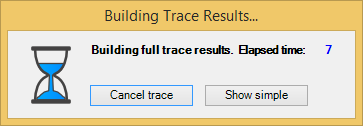
When you perform a trace, the dialog pictured here will appear after a few seconds. Click Cancel trace to stop a trace that is taking too long to build. Click Show simple to show the trace results without calculating their geometries. This will show the entire feature as opposed to showing only a portion of the complex edge. The Zoom to Results tool will be unavailable when showing a simple trace. 
|
Gas Tracing is available in ArcFM and ArcFM Viewer.
Cathodic protection trace with buffer