
| ArcFM Desktop Overview > ArcFM > Edit Tasks > Dot to Dot |
This edit task must be used with a template favorite. You may select it without a template and attempt to place features, but the edit task will NOT function.
The ArcFM Dot to Dot edit task lets you create a multi-part sketch that defines the location of features in a template favorite. Once the locations are defined, Dot-to-Dot automatically places the features on the map. Dot-to-Dot incorporates the ArcGIS context menu Sketch tools such as Length, Angle, Deflection, Absolute XY, and Parallel.
ArcFM Dot to Dot differs from Create ArcFM Feature in that it allows multi-part sketches. If you're using Create ArcFM Feature, the feature is placed at the first click. When using ArcFM Dot to Dot, the feature is placed at the point the user finishes the sketch.
The following is a very simple example to illustrate how ArcFM Dot to Dot works.
Sample template
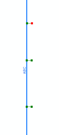
 The red box indicates the most recently Finish Part point. |
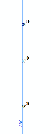
 When the sketch is finished, poles are placed at each point at which the user selected Finish Part. |
This edit task may also be used with linear features. In this case the points at which the user selects Finish Part serve as the vertices for the linear feature.
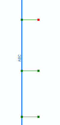
 The red box indicates the most recently Finish Part point. |
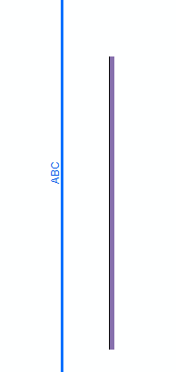
 When the sketch is finished, the Finish Part points are connected by the linear feature. |