
| ArcFM Desktop Overview > Designer > Design Optimization > Default Symbology |
Design Optimization uses layer-based default symbology. You can modify this symbology and turn layers on and off as you would any layer. Design Optimization default symbology layers are only available when Design Optimization is open. This section describes the behavior of the Design Optimization default symbology layers and how to modify this behavior. This section also describes the steps required to change the look of the symbols.
Default Symbology Behavior
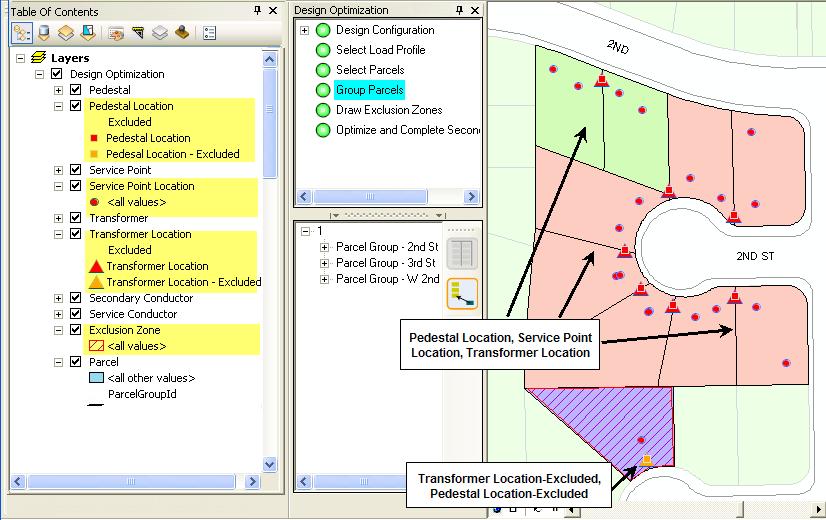
After you select and group your parcels (as shown in the following example), Design Optimization displays its symbology from the Pedestal Location, Service Point Location, Transformer Location, and Parcel layers. These symbols represent potential locations for the transformers, pedestals, and service points. Therefore, there can be more than one pedestal location, service point location, or transformer location displayed in any one parcel. Pedestal Location-Excluded and Transformer Location-Excluded symbology exists for those location features that reside within an exclusion zone.
The following example depicts Design Optimization's default symbology for grouped parcels. The active layers are highlighted in yellow in the Display tab for illustration purposes.
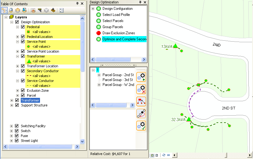
After you have optimized the design, Design Optimization displays its symbology from the Pedestal, Transformer, Secondary Conductor, and Service Conductor layers. The transformer layer displays a label denoting the kVA rating. You can turn on or off any layer's labels using the Labels tab on the Layers Properties dialog.
The following example depicts Design Optimization's default symbology for optimized parcels. The active layers are highlighted in yellow in the Display tab for illustration purposes.
 |
If the Pedestal Location, Service Point Location, Transformer Location, and/or Parcel layers are still displayed after optimizing, see the section entitled Automatically Turn off Location and Parcel Layers after Optimizing |
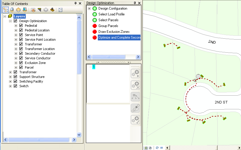
Once you complete the design, Design Optimization deactivates its default symbology.
Automatically Turn Off Location and Parcel Layers after Optimizing
If your Parcel, Pedestal Location, Service Point Location, or Transformer Location layers remain visible after you optimize a design, you can perform the following steps to automatically turn off these layers after optimizing:
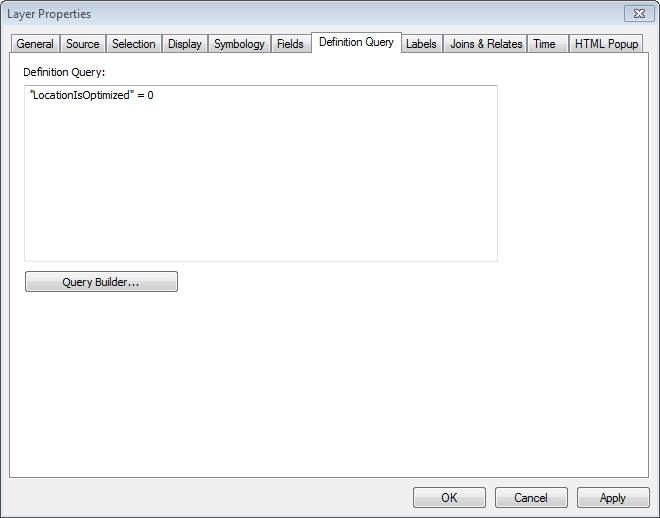
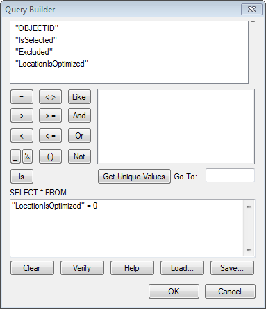
Example of a location layer definition query
 |
Alternatively, you can click Query Builder to use the Query Builder dialog box to construct a query as the following example depicts. |
