Using ArcFM Solution Desktop
Create Duct Connections
| ArcFM Desktop Overview > Conduit Manager > Underground Facility Manager > Create/Edit UFM Diagram > Create Duct Connections |
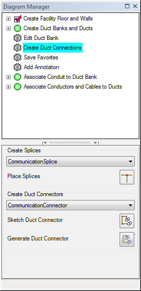
The Create Duct Connections task allows you to add connectors and splices to depict the travel of conduit through underground facilities such as vaults and manholes. This section describes how to use the Create Splices tool to add splices and the Create Duct Connections tool to add connectors to an underground facility.
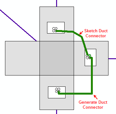
Two tools are available to create connectors: 1) Generate Duct Connector and 2) Sketch Duct Connector. The Generate Duct Connector tool automatically draws connections between ducts using straight lines. The Sketch Duct Connector tool allows you to draw the line on the map yourself using vertices.
 and select the first duct and then the second duct. The connector is automatically drawn between the two selected ducts.
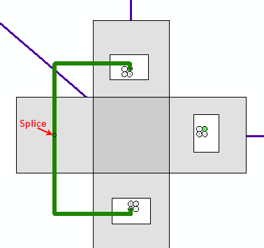
 and add the splice to the map using the splice cursor
  . and click a duct and then click the splice (or vice-versa). A connector line is automatically drawn between the duct and the splice. Continue drawing connectors to the splice in the same manner. The connection between ducts and splices are automatically drawn on the map as shown in the following example.
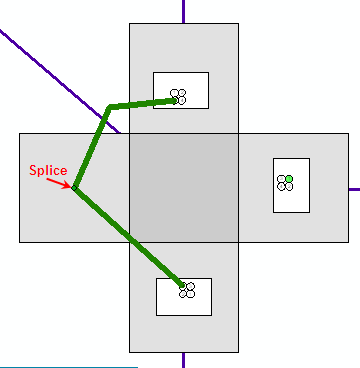
 and select a duct to start the sketch. Draw a sketch with as many vertices as needed. Complete the sketch by clicking on the second duct. and add the splice to the map using the splice cursor . and click a duct or splice to start the sketch. Draw the connector with as many vertices as needed and click the subsequent duct or splice to finish the sketch. The following example depicts connectors drawn on a map using Sketch Duct Connector.
 |
Turn off snapping to duct features when using the Sketch Duct Connector. |