
| ArcFM Desktop Overview > ArcFM > Phase Swap > Interpreting Trace Results |
The Phase Swap tool must perform a trace to locate the tap point and identify the features that will participate in the phase swap operation. In a geometric network that supports complex edges, phase swap tracing takes into account the individual elements of these complex edges when displaying results. The following examples are scenarios that might help clarify how these trace results may appear.
Tap Point: The tap point is the location at which the phase swap operation is initiated. There are two methods for determining the tap point (Automatic and Manual). These are discussed on the Phase Swap Options page.
Click Point: The click point is the point at which the user clicks on the map. The click point is denoted with a green square.
When the Phase Swap tool is executed, all features that will participate in the phase swap operation are highlighted in red on the map.
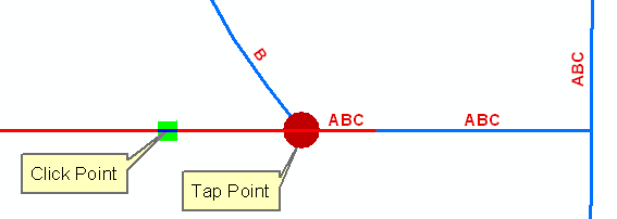
Barrier is upstream of the click point
The Phase Swap trace ignores barriers when identifying the tap point and respects them when tracing downstream to identify features that will participate in the phase swap operation.
Figure 1-1, In this example, the Locate Tap Point option is set to Automatic. The tool ignores the barrier when locating the tap point, and respects the barrier when identifying features downstream to participate in the phase swap operation.
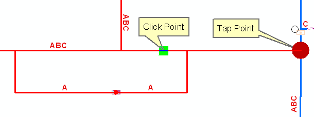
Manual tap point appears in the middle of a complex edge
When locating the tap point using the Manual Locate Tap Point option, the Phase Swap trace locates the first upstream junction from the click point. As depicted in the example below, the tap point may occur on a junction in the middle of a complex edge.

Figure 2-1, In this example, the Locate Tap Point option is set to Manual. The tap point appears to be in the middle of the conductor. The phase swap trace identified the junction at which the A phase line connects with the ABC phase line.
Automatic tap point is at an intersection of like-phase conductors
The Phase Swap trace locates the upstream junction nearest the click point and identifies it as the tap point. On a complex edge, the tap point could appear in the middle of a conductor feature (see Figure 3-1). The conductor will be swapped, but any conductors connected to it upstream of the tap point will not be included in the phase swap operation.
Figure 3-1, In this example, the Locate Tap Point option is set to Automatic. The Phase Swap trace locates the nearest upstream junction and identifies it as the tap point. Because the A phase line in blue is not downstream of the tap point, it is not included in the phase swap operation.

Figure 3-2, In this example, the Locate Tap Point option is set to Automatic. The trace locates the identifies upstream junction as the tap point. All features downstream of the tap point are included in the phase swap operation.