Using ArcFM Solution Desktop
Fiber Trace Schematics

| ArcFM Desktop Overview > Fiber Manager > Fiber Manager Schematics > Fiber Trace Schematics |
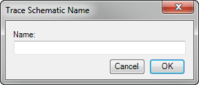
You can create a schematic diagram based on a fiber trace. Fiber trace schematics adhere to all fiber user settings.
 on the Fiber Manager Toolbar.
 |
For directional traces, if you clicked the wrong feature, you can press ESCAPE to reset the tool before specifying a trace direction. |
Fiber Manager generates and activates the new fiber trace schematic.
 |
The first time you generate a fiber trace schematic you may notice large boxes surrounding implied connections. All subsequently generated fiber trace schematics scale this box correctly. To correctly scale such boxes on your first fiber trace schematic, click Start Editing Diagram  then Stop Editing Diagram then Stop Editing Diagram  on the Schematic Editor toolbar. on the Schematic Editor toolbar. |