
| ArcFM Desktop > ArcFM > Feeder Manager > Feeder Manager Step 9: Build Geometric Network |
If your data set does not already have a geometric network, you will need to create one. The steps on this page walk through how the geometric network MAY be created. This is not necessarily the best way to create the network for your geodatabase. You may wish to select different options than those selected here. The Build Geometric Network tool is an Esri tool. Refer to the Esri online help for more detailed information about this functionality.
The most important points to keep in mind while building the geometric network are: be sure to include all feature classes that you listed; be sure to specify an appropriate snapping tolerance.
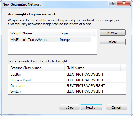
Network weights are what make tracing tasks work. Weights are assigned during the process of building the geometric network. (For more information, see ArcGIS Help, Creating a New Geometric Network.) These steps assume that you have created features that you want to participate in tracing tasks with a field that will be assigned model name MMELECTRICTRACEWEIGHT to which is assigned the MMElectricTraceWeight (exact spelling and capitalization) weight. Check for build errors after the wizard is finished.
|
Feature Class |
Role |
|---|---|
|
Busbar |
Complex Edge |
|
DeliveryPoint |
Simple Junction |
|
DynamicProtectiveDevice |
Simple Junction |
|
ElecGeomNetwork_Junctions |
Simple Junction |
|
Fuse |
Simple Junction |
|
Generator |
Simple Junction |
|
MiscNetworkFeature |
Simple Junction |
|
OpenPoint |
Simple Junction |
|
PFCorrectingEquipment |
Simple Junction |
|
PrimaryMeter |
Simple Junction |
|
PriOHElectricLineSegment |
Complex Edge |
|
PriUGElectricLineSegment |
Complex Edge |
|
SecOHElectricLineSegment |
Complex Edge |
|
SecUGElectricLineSegment |
Complex Edge |
|
ServicePoint |
Simple Junction |
|
Streetlight |
Simple Junction |
|
Switch |
Simple Junction |
|
Transformer |
Simple Junction |
|
VoltageRegulator |
Simple Junction |

When the wizard has finished building your network, search your database for a table whose name contains _BUILDERR. If no such table exists then there are no problems with your new network and it need not be rebuilt. If the build errors table does exist, consult the ArcGIS online documentation to learn the significance of its contents and take any necessary measures to eliminate the problems it indicates. After eliminating the causes of any network build errors, you must drop the network (and the build errors table) and build again until you get no build errors.