
| Appendix > Fiber Manager Data Model > Additional Information > Numbering Scheme - Fiber |
Version: 10.1 |
This section describes how cards and ports are numbered within a patch panel.

Figure 1
The cards and ports within a patch panel are numbered starting from the upper left corner at the number 1 position (see Figure 1). Each position number increments by one while moving to the right. The next rows numbering starts on the left hand side and continues to the end of the row on the right, where the process starts over again.

Figure 2
This is an example of how this example works with a 1 column and 8 rows.

Figure 3
This example shows how this system works when there are 8 columns and 1 row.

Figure 4
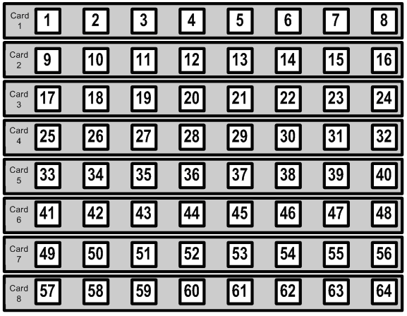
This example shows how both cards and ports follow the same numbering scheme. Each card contains a set of ports that have 8 columns and 1 row. The cards themselves are arranged horizontally in a grid that has 1 column and 8 rows.

Figure 5
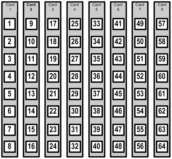
This example shows each card have ports arranged in a grid that has 1 column and 8 rows. The cards are arranged vertically in a grid that has 8 columns and 1 row.

Figure 6
This example shows each card having a port arrangement of 4 columns and 1 row. The cards are arranged horizontally in a 2 columns with 8 rows.

Figure 7
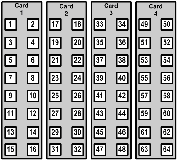
This example shows the ports arranged in 2 columns or 8 rows. The cards are arranged vertically in 4 columns of 1 row.

Figure 8
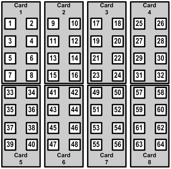
This example shows the ports arranged in 2 columns of 4 rows on each card. Each card is arranged vertically in 4 columns of 2 rows.
The arrangement of the ports and cards is controlled by a number of fields. These fields have required model names, so that the Fiber Manager application can locate the information and use it correctly.
The model names that are important for patch panel card placement are:
The model names that are important for port placement are: