
| Appendix > Fiber Tracing Types |
Version: 10.1 |
Fiber Manager conducts Y-style tracing by default. You can enable X-style tracing in the Fiber User Settings window.
For tracing purposes, an X-style network is either of the following:
If you have an X-style network:
If you have a Y-style network:
X-style tracing allows you to trace how light behaves when sophisticated features, such as passive combining splitters, are part of your network. X-style tracing includes fibers that go through all input and output features and that branch either direction, whether they are going upstream or downstream. The results of an X-style trace depends on the settings assigned to the selected features.
The following image shows some of the results X-style tracing provides that Y-style tracing does not. The orange arrow represents light traveling into a splitter. The blue and green arrows represent the paths light could travel away from a splitter. Blue arrows indicate an output port and green an input port.
Trace results a and d show light traveling downstream into the splitter (from an input port) and then continuing downstream through the two top branches (output ports) and upstream through the other bottom branch (input port). Trace results b and c show light traveling upstream into the splitter (from an output port) and then continuing upstream through the bottom two branches (input ports) and downstream through the other top branch (output port).

For more information about the interior of the splitter feature refer to the "A Look Inside the X-Style Splitter" section at the bottom of this page.
The other trace option is Y-style tracing, which limits results to fibers that branch outward when going downstream and fibers that branch inward when going upstream. For example, when light enters the bottom branch of the "Y" it leaves through the top two branches. If light was returning through one of the top branches, it would travel through only the bottom branch.
The image below shows sample results of Y-style tracing. Note that with a split arranged in an X-style instead of a Y-style, the Y-style trace results would not include everything you might expect. The orange arrow represents light traveling into a splitter. The blue and green arrows represent the paths the light would travel away from a splitter. Blue arrows indicate an output port and green an input port. The gray fibers represent the fibers Y Style tracing would not include in its results.
The first two results show light traveling downstream into a splitter and then continuing downstream through the top branches (output ports). Y-style style tracing would not include the additional branch of the X-style arrangement. The last two results show light traveling upstream into a splitter and then continuing upstream through one bottom branch (input port). Y-style tracing would not include the additional top and bottom branches of the X-style arrangement.

For more information about the interior of the splitter feature refer to the "A Look Inside the Y-Style Splitter" section at the bottom of this page.
The Fiber Trace tool starts its trace on a specific fiber and uses the connectivity information at each junction to determine the fiber's path in both directions. The directional tracing option limits trace results to the one direction you select.
The examples below show the results of a trace that includes both connections and the results of a trace that used directional tracing. In the first example, strand 26 of The Johnston BB46 fiber cable was traced without directional tracing. The trace results include the connections to both NOC BB4 and Dover BB89. The next example used directional tracing. The trace results include only the selected direction, which was Dover BB89.
|
Trace result that includes both connections |
Trace result that includes single connection selected through directional tracing |
If you run a Y-style trace on an X-style network the results will be inconsistent. This is because the Y-style trace randomly chooses its initial direction and does not travel on paths not configured in a Y-style which means it skips some branches you would expect to have in an X-style trace. However, you can run a Y-style trace on an X-style network (or a network containing X-style devices) if you run a directional trace. In this case, the Y-style trace prompts the user to select a direction when it's initialized.
An X-style trace may be run on either type of network as it traces in all directions. You can enable a directional trace while running an X-style trace, and you will see X-style results returned from only the chosen direction.
|
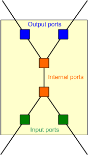
The image to the right illustrates the insides of an X-style splitter. The pale yellow box represents the Splitter feature. Inside are the ports which are represented in the geodatabase by relationships. The orange boxes in the middle represent internal ports. These internal ports are connected to each other through the Connection Manager (manual connections). In the geodatabase, the SplitterInConnector and SplitterOutConnector objects may represent internal ports. The blue boxes represent output ports. In the geodatabase, these features may be modeled using the SplitterOutputPort object. Each output port inside the splitter has an implied connection to an internal port (e.g., SplitterOutConnector). The green boxes represent input ports. In the geodatabase, these features may be modeled using the SplitterInputPort object. Each input port inside the splitter has an implied connection to an internal port (e.g., SplitterInConnector). |
 |
 |
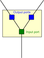
The image to the left illustrates the contents of a Y-style splitter. The pale yellow box represents a Y-style splitter. The ports inside the splitter are represented in the geodatabase by relationships. Unlike the X-style splitter, the Y-style splitter does not have any internal ports. Each Y-style splitter has only output and input ports. The image shows that the Y-style splitter has one input port and two output ports. However, a Y-style splitter may have any number of output ports, and only one input port. The blue boxes represent output ports. In the geodatabase, these features may be modeled using the SplitterOutputPort object. The green box represents an input port. In the geodatabase, these features may be modeled using the SplitterInputPort object. The input and output ports have implied connections to one another. |